Image pickup apparatus with rotary lens barrel

Active Publication Date: 2008-03-20
SONY CORP
View PDF74 Cites 39 Cited by
  • Summary
  • Abstract
  • Description
  • Claims
  • Application Information

AI Technical Summary

Benefits of technology

[0012]An image pickup apparatus with a rotary lens barrel according to an embodiment of the present invention includes a lens barrel, a hollow shaft, a base, electric wiring, and a protection member. The lens barrel has a lens and an image pickup device embedded therein. The hollow shaft is rotatable about an axis intersecting with an optical axis of the lens. The axis serves as a central axis of the hollow shaft. The base supports the lens barrel in a rotatable manner by using the hollow shaft. The electric wiring extends through the inside of the hollow shaft to electrically transmit an image pickup signal of the image pickup device. The protection member is provided in the hollow shaft so as to prevent the electric wiring from coming into contact with the hollow shaft.
[0013]With this configuration, the lens barrel having the lens and the image pickup device embedded therein is rotated by way of the hollow shaft about the central axis, or the axis intersecting with the optical axis of the lens. The electric wiring for electrically transmitting the image pickup signals of the image pickup device extends through the inside of the hollow shaft. Therefore, since the electric wiring extends through the rotation center of the lens barrel even while the lens barrel is rotated, the electric wiring can be easily arranged at the rotation portion. Also, since the electric wiring extends through the shortest path, the length of the electric wiring in the

Problems solved by technology

With the configuration disclosed in the publication, the electric wiring can be easily arranged at the rotation portion of the lens barrel, however, the electric wiring may be easily damaged, resulting in deterioration of the durability.
If the coating of the electric wiring is damaged due to wear of the coating or the like, the electric wiring may suffer from short-circuit etc.
Due to this, the electric wiring may use a h

Method used


Image

  • Image pickup apparatus with rotary lens barrel
  • Image pickup apparatus with rotary lens barrel
  • Image pickup apparatus with rotary lens barrel

Examples


Example

[0024]An embodiment of the present invention is described below with reference to the drawings.

[0025]Though described in detail below, in this embodiment, a video camera 10 for video conferences is used as an example of an image pickup apparatus with a rotary lens barrel. The video camera 10 in this embodiment can electrically transmit image pickup signals with a high-definition (HD) image quality, by using an image pickup device 32 such as a charge coupled device (CCD) image sensor or a complementary metal oxide semiconductor (CMOS) image sensor.

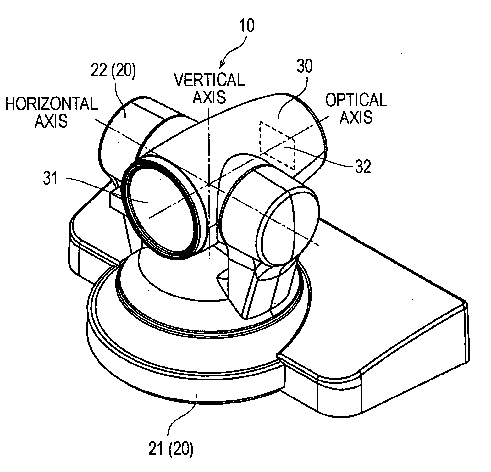
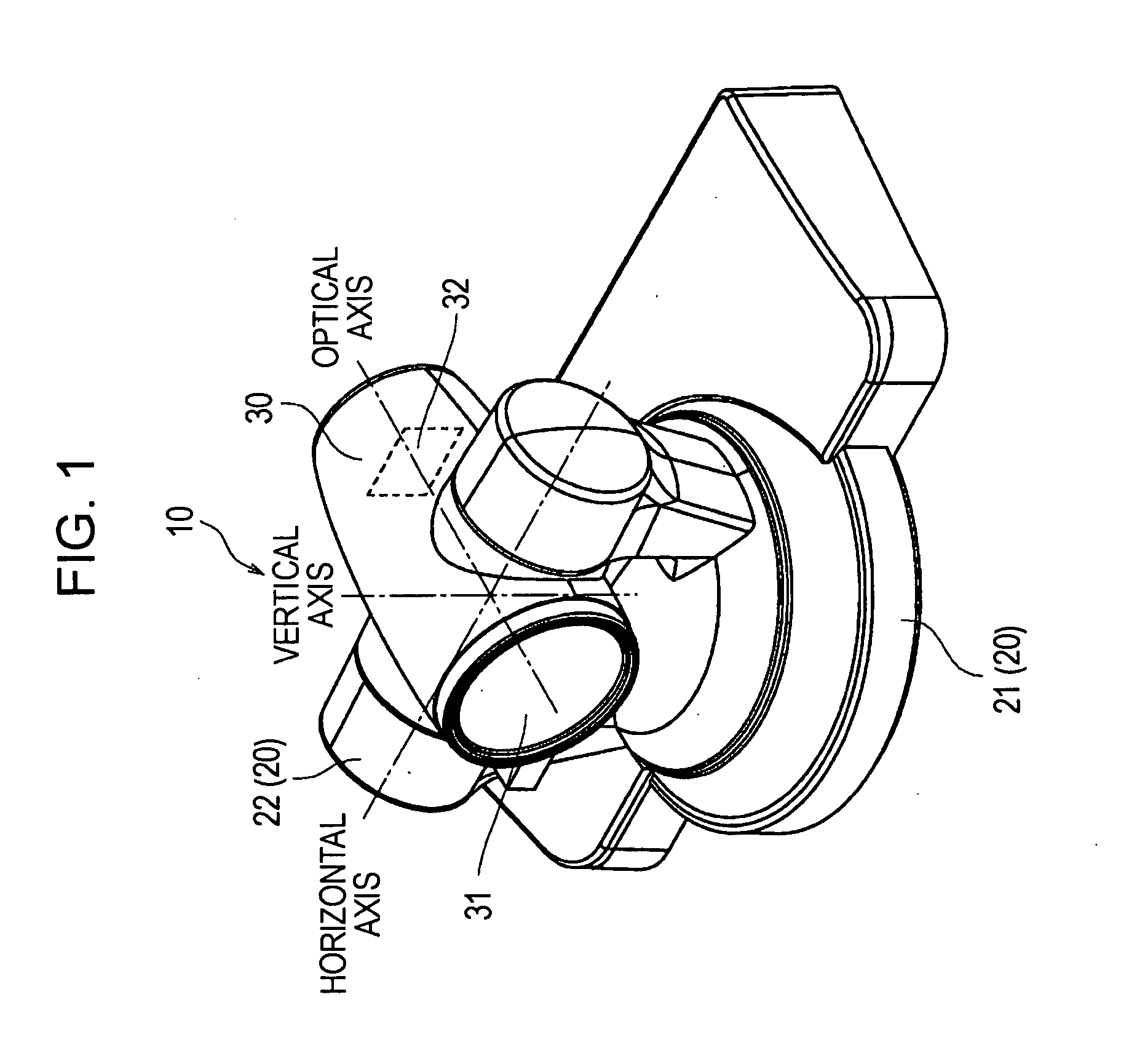
[0026]FIG. 1 is a perspective view showing the video camera 10 in this embodiment.

[0027]As shown in FIG. 1, the video camera 10 in this embodiment is installed in a conference room or the like by using a base 20, so that the video camera 10 may be used for video conferences etc. The base 20 includes a stationary sub-base 21 for installing the video camera 10 in the conference room or the like, and a rotary sub-base 22 that is rotatable with...


PUM


Abstract

An image pickup apparatus includes a lens barrel, a hollow shaft, a base, electric wiring, and a protection member. The lens barrel has a lens and an image pickup device embedded therein. The hollow shaft is rotatable about an axis intersecting with an optical axis of the lens. The axis serves as a central axis of the hollow shaft. The base supports the lens barrel in a rotatable manner by using the hollow shaft. The electric wiring extends through the inside of the hollow shaft to electrically transmit an image pickup signal of the image pickup device. The protection member is provided in the hollow shaft so as to prevent the electric wiring from coming into contact with the hollow shaft.

Description

CROSS REFERENCES TO RELATED APPLICATIONS[0001]The present invention contains subject matter related to Japanese Patent Application JP 2006-249647 filed in the Japanese Patent Office on Sep. 14, 2006, the entire contents of which are incorporated herein by reference.BACKGROUND OF THE INVENTION[0002]1. Field of the Invention[0003]The present invention relates to an image pickup apparatus with a rotary lens barrel in which a lens barrel having a lens and an image pickup device embedded therein is rotatable. In particular, the present invention relates to a configuration capable of decreasing the length of electric wiring for electrically transmitting image pickup signals, reducing influence of noise applied to the image pickup signals, and markedly improving durability of the electric wiring.[0004]2. Description of the Related Art[0005]An example of an image pickup apparatus with a rotary lens barrel may be a video camera for video conferences and a video camera for surveillance. In su...

Claims


Application Information

Patent Timeline
IPC IPC(8): H04N5/225
CPCH04N5/2251H04N5/217H04N23/81H04N23/55
Inventor HIDA, HIROAKITERADA, HIROTSUGU
Owner SONY CORP
Why Eureka
Try Eureka