Liquid crystal display device

a liquid crystal display and display device technology, applied in the field of liquid crystal display devices, can solve the problems of increasing power consumption, lowering image quality, unstable video signal potential, etc., and achieve the effects of preventing image quality deterioration, reducing image quality, and reducing the polarity of video signals

Active Publication Date: 2008-03-20
PANASONIC LIQUID CRYSTAL DISPLAY CO LTD +1
View PDF11 Cites 85 Cited by
  • Summary
  • Abstract
  • Description
  • Claims
  • Application Information

AI Technical Summary

Benefits of technology

[0028]According to the present invention, by allowing the liquid crystal display panel which adopts the double-scanning line method to perform common inversion driving, a heat value of the data drive can be lowered thus preventing the deterioration of image quality.
[0029]Further, according to t

Problems solved by technology

However, in case of the liquid crystal display panel having the pixel constitution shown in FIG. 7, for example, the number of drive circuits (data drivers) which generate video signals (gradation voltages) which are inputted to the respective video signal lines DL is increased thus giving rise to drawbacks that the power consumption is increased, and a potential of the video signal becomes unstable along with the increase of heat value of the data driver thus lowering image quality, for example.
Accordingly, for example, there may be a case that stripes in the longitudinal direction appear on a display screen thus lower

Method used


Image

  • Liquid crystal display device
  • Liquid crystal display device
  • Liquid crystal display device

Examples


Embodiment Construction

[0046]Hereinafter, the present invention is explained in detail in conjunction with an embodiment by reference to drawings.

[0047]Here, in all drawings for explaining the embodiment, parts having identical functions are given same symbols and their repeated explanation is omitted.

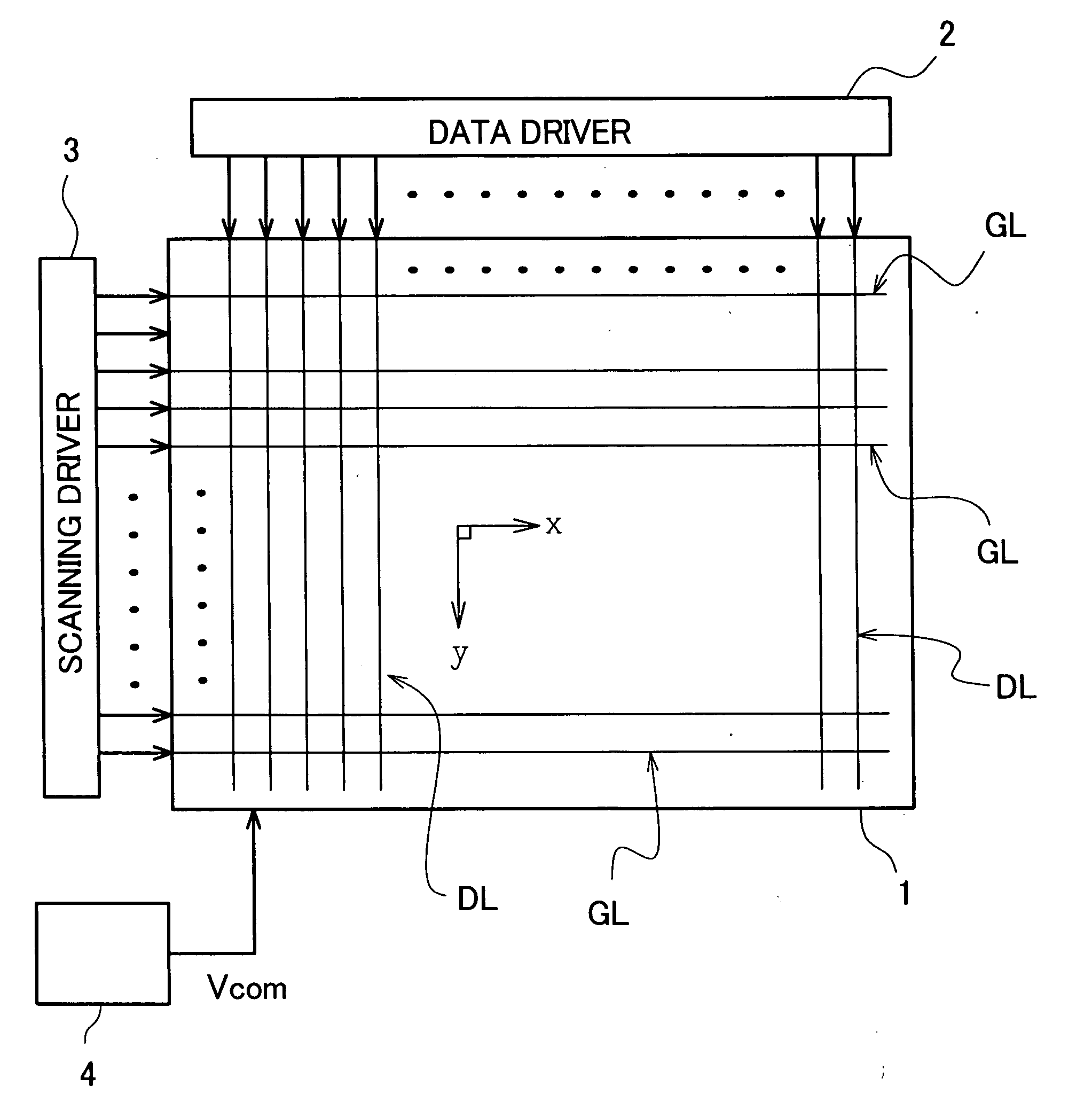
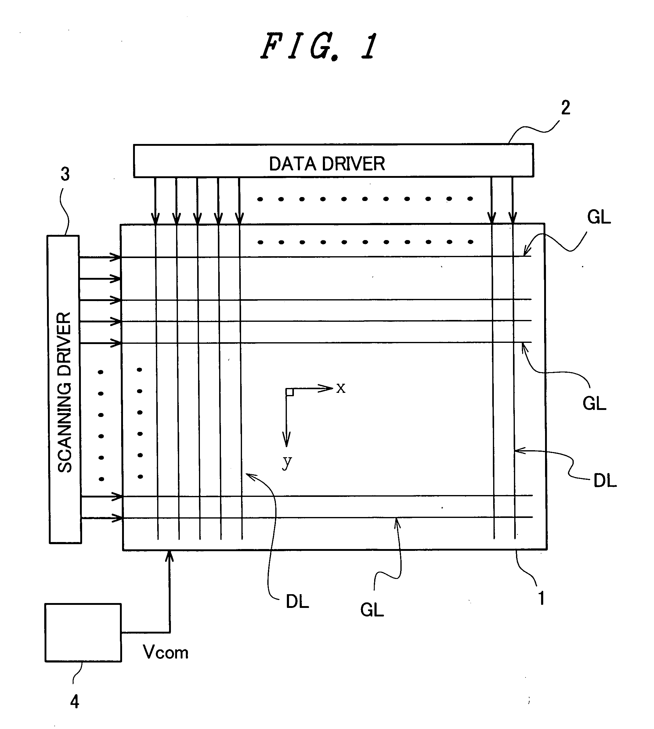
[0048]FIG. 1 is a schematic block diagram showing the schematic constitution of a liquid crystal display device of one embodiment according to the present invention.

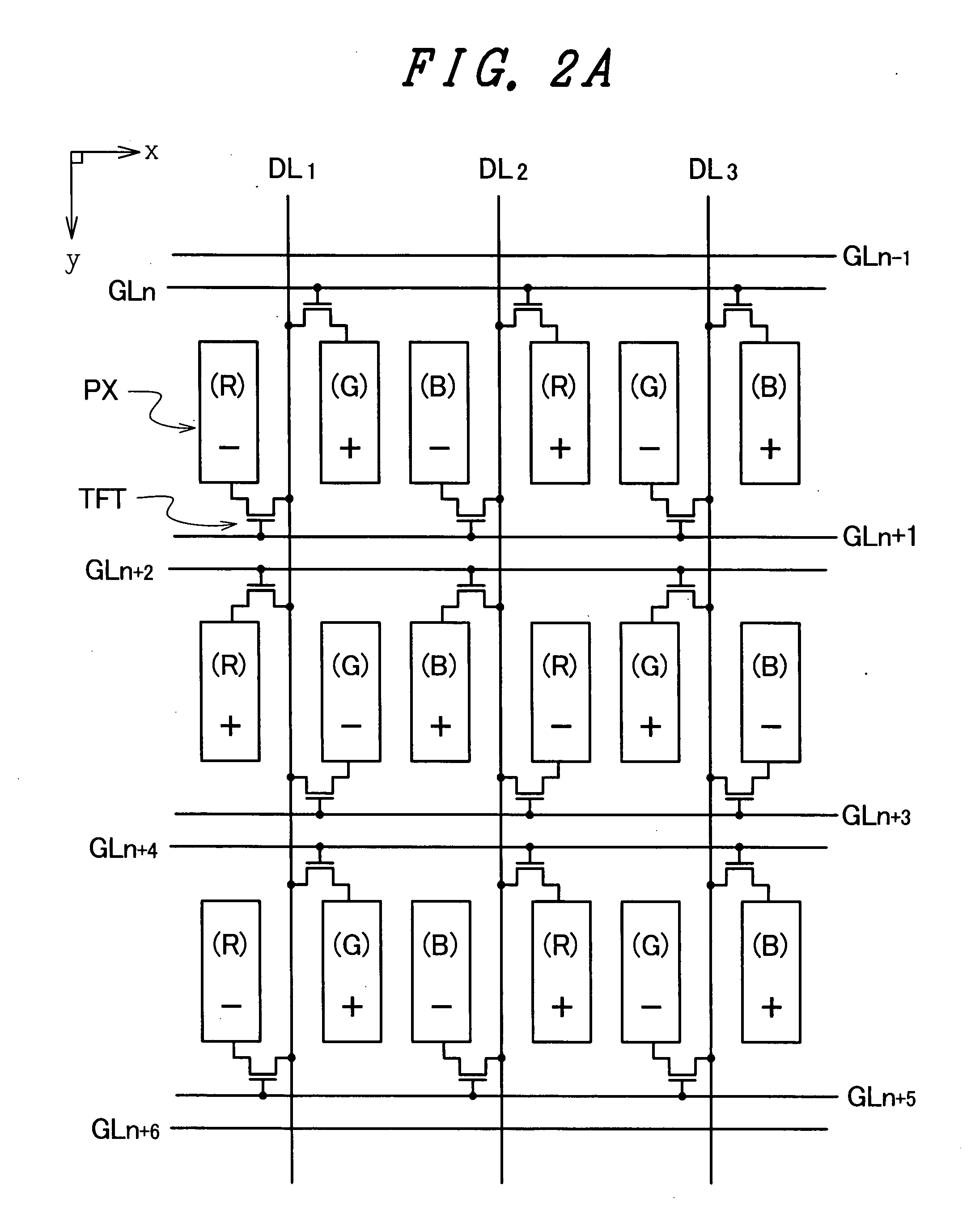
[0049]FIG. 2A is a schematic circuit diagram showing one constitutional example of a liquid crystal display panel of the embodiment and polarities of pixel electrodes within 1 frame period. FIG. 2B is a schematic view showing one example of a driving method of the liquid crystal display panel having the constitution shown in FIG. 2A.

[0050]The liquid crystal display device to which the present invention is applied includes, for example, as shown in FIG. 1, a liquid crystal display panel 1 having a plurality of video signal lines DL which extends i...


PUM


Abstract

The present invention prevents deterioration of image quality by lowering a heat value of a data driver connected to a liquid crystal display panel. In a liquid crystal display device, a pixel which connects a TFT thereof to one of two neighboring scanning signal lines and a pixel which has a TFT thereof connected to the other scanning signal line are alternately arranged in the extending direction of the scanning signal lines, two pixels which are arranged close to each other with one video signal line sandwiched therebetween have respective TFTs connected to the video signal line, and the connection relationship between the TFT of each pixel and the scanning signal line is inverted for every pair of two pixels arranged in the extending direction of the video signal lines. Here, each time the scanning signal line to which a scanning signal is inputted is changed, a potential of a common voltage is alternately changed over between a first potential and a second potential higher than the first potential, a video signal of a potential higher than the first potential is inputted to the video signal lines when the common voltage of the first potential is inputted to the common electrode, and a video signal of a potential lower than the second potential is inputted to the video signal lines when the common voltage of the second potential is inputted to the common electrode.

Description

[0001]The present application claims priority from Japanese application JP2006-250989 filed on Sep. 15, 2006, the content of which is hereby incorporated by reference into this application.BACKGROUND OF THE INVENTION[0002]1. Field of the Invention[0003]The present invention relates to a liquid crystal display device, and more particularly to a technique which is effectively applicable to a liquid crystal display device having high resolution such as a liquid crystal television receiver set.[0004]2. Description of the Related Art[0005]Conventionally, an active-matrix-type liquid crystal display device has been used in a liquid crystal television receiver set and the like, for example. The active-matrix-type liquid crystal display device includes a liquid crystal display panel which seals a liquid crystal material between a pair of substrates, and switching elements (also referred to as active elements) such as TFTs are arranged in a matrix array on one substrate out of the pair of su...

Claims


Application Information

Patent Timeline
IPC IPC(8): G06F3/038H04N3/14
CPCG09G3/3607G09G2300/0426G09G3/3648G09G3/3614
Inventor MORI, IKUKOONO, KIKUO
Owner PANASONIC LIQUID CRYSTAL DISPLAY CO LTD
Why Eureka
Try Eureka