
Outside plant cabinet thermal system

a plant cabinet and thermal system technology, applied in the field of cabinets, can solve the problems contaminant may be pulled into the cabinet and heat exchanger, etc., and achieve the effects of reducing the performance ability of the heat exchanger, compact overall size, and improved radiant heating of the cabin

Inactive Publication Date: 2008-03-20
COMMSCOPE INC
View PDF17 Cites 50 Cited by
  • Summary
  • Abstract
  • Description
  • Claims
  • Application Information

AI Technical Summary

Benefits of technology

[0012] With the cabinets of the prior art, outside air, which is drawn into the cabinet for use by the heat exchanger, is taken from a location close to the ground level. Contaminants (e.g., pollen, dust, weeds, grass clippings, seeds, crawling insects) are primarily located at or near the ground level of the cabinet. Therefore, contaminants may be pulled into the cabinet and heat exchanger. Although these contaminants do not enter the equipment chamber of the cabinet due to the separation between the outside air flow and the interior air flow within the heat exchanger, these contaminants can decrease the performance ability of the heat exchanger and lead to periodic maintenance requirements to clear the accumulated contaminants from the outside air path within the cabinet.
[0013] The Applicants have also appreciated that the radiant heating of the cabinet could be greatly improved by a system to cool one or more of the outer walls of the cabinet. The Applicants have also appreciated a need in the art for a cabinet which improves on one or more of the following attributes: (A) minimization of acoustic noise from active components within the cabinet (such as fans); (B) a more Compact overall size and increased density of electronic equipment within the housing; (C) a more streamlined outer housing shell; (D) a better directing of air flow to optimize the cooling effects within the cabinet; and (E) a fan redundancy to ensure performance in the case of a fan failure.
[0014] The Applicants have also appreciated a need for a cabinet which is simple in design, rugged, more flexible as to end uses, easy to manufacture and / or less expensive to manufacture.

Problems solved by technology

Therefore, contaminants may be pulled into the cabinet and heat exchanger.
Although these contaminants do not enter the equipment chamber of the cabinet due to the separation between the outside air flow and the interior air flow within the heat exchanger, these contaminants can decrease the performance ability of the heat exchanger and lead to periodic maintenance requirements to clear the accumulated contaminants from the outside air path within the cabinet.

Method used


Image

  • Outside plant cabinet thermal system
  • Outside plant cabinet thermal system
  • Outside plant cabinet thermal system

Examples


Embodiment Construction

[0027] The present invention now is described more fully hereinafter with reference to the accompanying drawings, in which embodiments of the invention are shown. This invention may, however, be embodied in many different forms and should not be construed as limited to the embodiments set forth herein; rather, these embodiments are provided so that this disclosure will be thorough and complete, and will fully convey the scope of the invention to those skilled in the art.

[0028] Like numbers refer to like elements throughout. In the figures, the thickness of certain lines, layers, components, elements or features may be exaggerated for clarity. Broken lines illustrate optional features or operations unless specified otherwise.

[0029] The terminology used herein is for the purpose of describing particular embodiments only and is not intended to be limiting of the invention. Unless otherwise defined, all terms (including technical and scientific terms) used herein have the same meaning...


PUM


Abstract

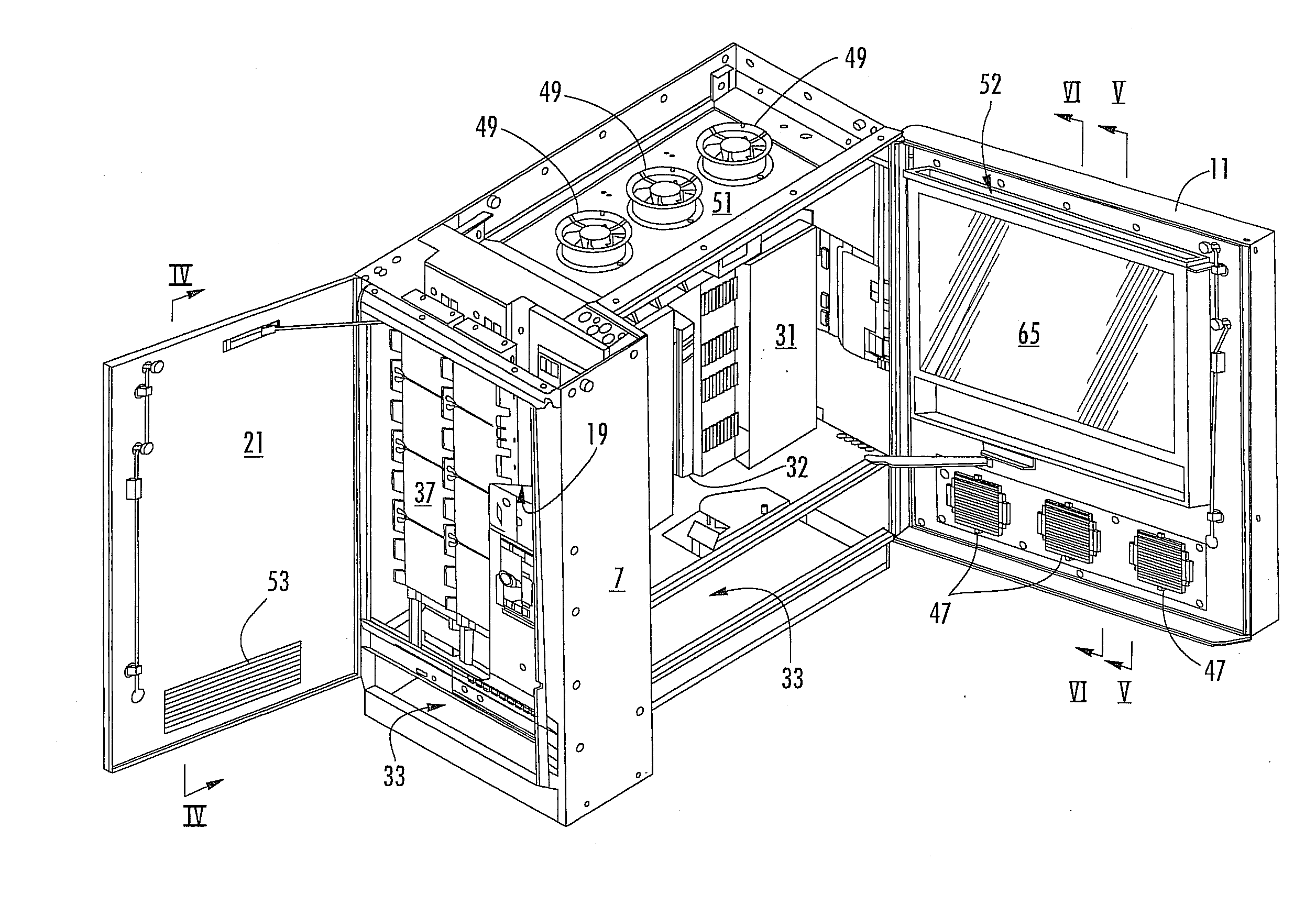
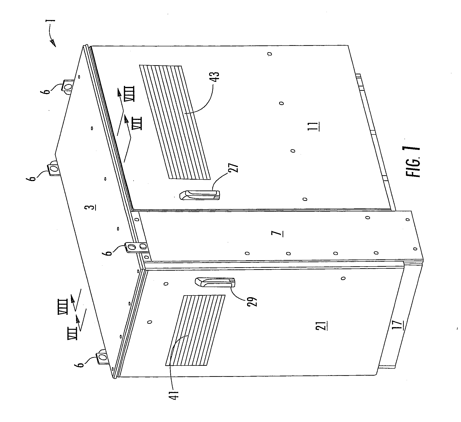
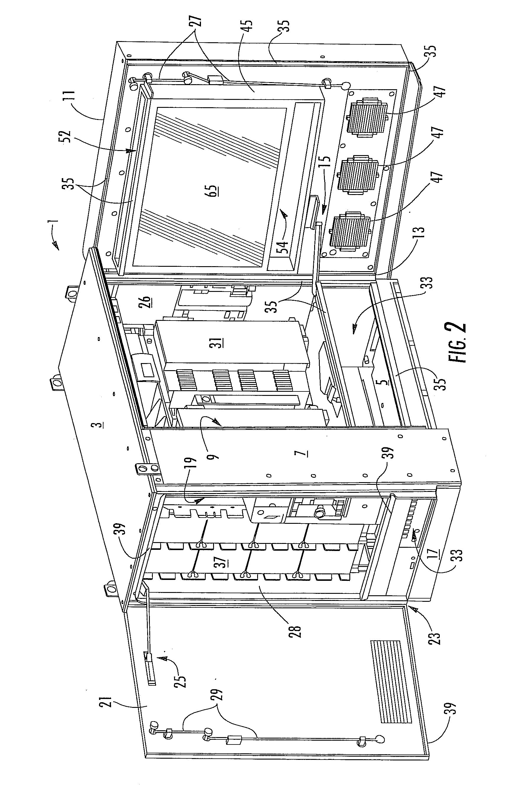
An outdoor equipment cabinet includes a housing with a first door for accessing an equipment compartment within the housing. A battery compartment is located proximate a bottom of the housing. First and second air vents are located in an upper half of the cabinet. At least one fan moves air from the first vent, down to the battery compartment and then up and out of the second vent. In some embodiments, the first door includes the second vent, and a dual wall construction leading to a heat exchanger mounted to the first door. Air passes through the dual wall construction of the first door and through the heat exchanger to regulate an air temperature within the equipment compartment, and then passes out the second vent. The first vent may be provided in a second door which also includes a dual wall construction to guide incoming air to the battery compartment.

Description

[0001] This application claims the benefit of U.S. Provisional Application No. 60 / 845,762, filed Sep. 20, 2006, the entire contents of which are herein incorporated by reference.BACKGROUND OF THE INVENTION [0002] 1. Field of the Invention [0003] The present invention relates to a cabinet. More particularly, the present invention relates to an outdoor cabinet for housing communications equipment, which includes a thermal regulating system to maintain an internal temperature of the cabinet within prescribed limits. [0004] 2. Description of the Related Art [0005] There are many types of optical and electronic equipment that must be located in an outdoor environment. For example, telecommunication equipment, networking equipment, and cable television equipment (generally referred to as “communication equipment”) are often housed in an enclosure or cabinet located outdoors. In the communications industry, such equipment is often referred to as “outside plant equipment”. Outside plant equ...

Claims


Application Information

Patent Timeline
IPC IPC(8): H05K7/20H05K5/02
CPCH05K7/206
Inventor HENDRIX, MARKBARTEK, DAVIDMANN, CHUCKYEH, JOSEPH
Owner COMMSCOPE INC
Learn More