Heat-dissipating device for back light source for flat panel display

a flat panel display and heat dissipation device technology, applied in the field of heat dissipation devices, can solve the problems of poor unsatisfactory heat dissipation efficiency of back light units, and achieve the effect of prolonging the life of flat panel displays and improving heat dissipation efficiency

Inactive Publication Date: 2008-03-20
SUNONWEALTH ELECTRIC MACHINE IND
View PDF16 Cites 28 Cited by
  • Summary
  • Abstract
  • Description
  • Claims
  • Application Information

AI Technical Summary

Benefits of technology

[0008]An object of the present invention is to provide a heat-dissipating device for a back light source for a flat panel display with enhanced heat-dissipating efficiency to thereby prolong the life of the flat panel display.

Problems solved by technology

However, the heat-dissipating efficiency for the back light units 6 is unsatisfactory, since the heat generated by the back light units 6 are indirectly conducted via the circuit board 7 to the heat-dissipating board 9.
The heat-conducting effect of the circuit board 7 is low, leading to poor heat-dissipating efficiency of the back light units 6.

Method used


Image

  • Heat-dissipating device for back light source for flat panel display
  • Heat-dissipating device for back light source for flat panel display
  • Heat-dissipating device for back light source for flat panel display

Examples


first embodiment

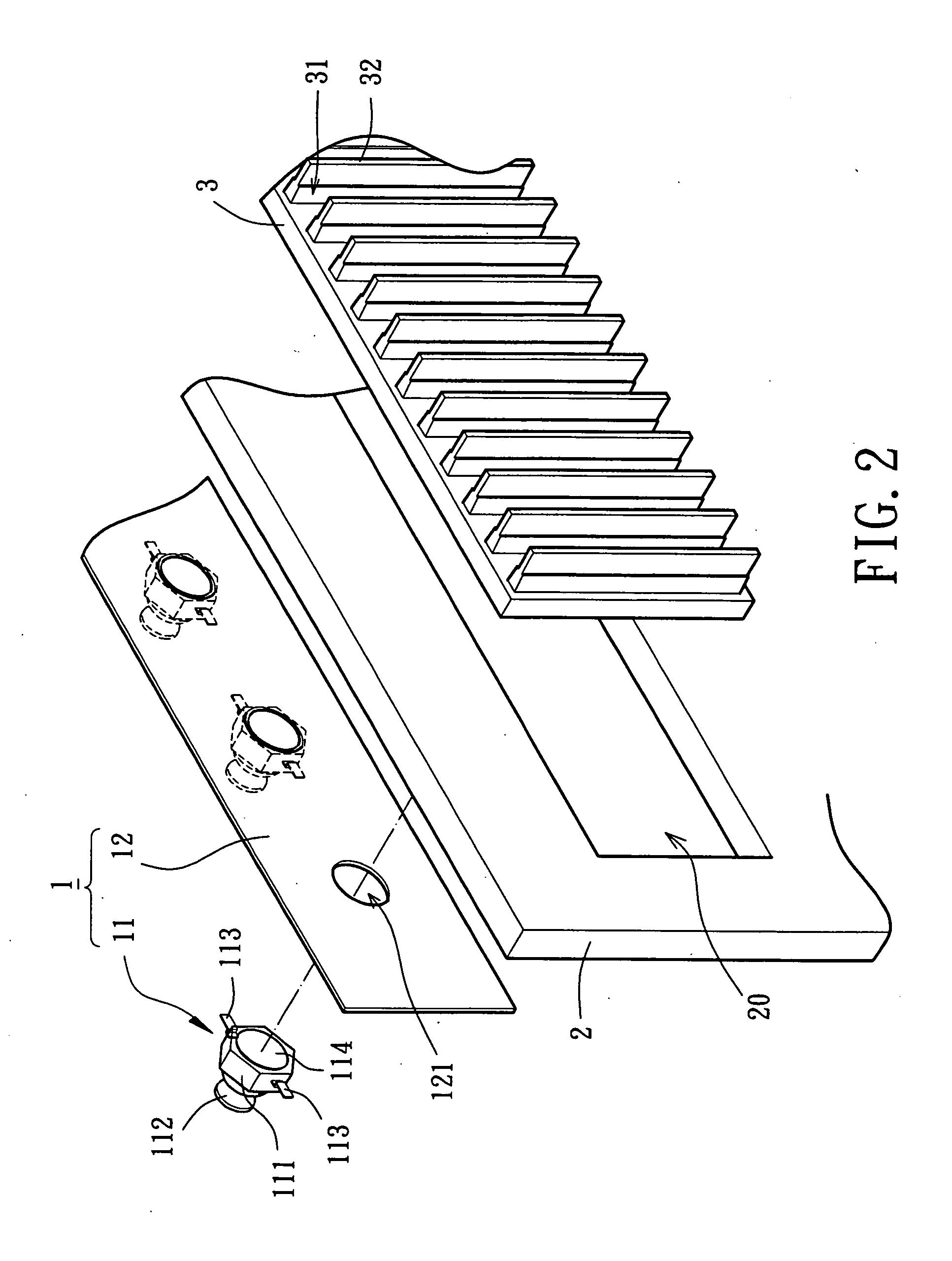
[0035]Referring to FIGS. 2 and 4, a heat-dissipating device for a back light source for a flat panel display in accordance with the present invention is preferably coupled to a rear side of a flat panel display (FPD) “a” that is preferably a liquid crystal display (LCD) or a plasma display panel (PDP). The heat-dissipating device provides back light while proceeding with heat dissipation.

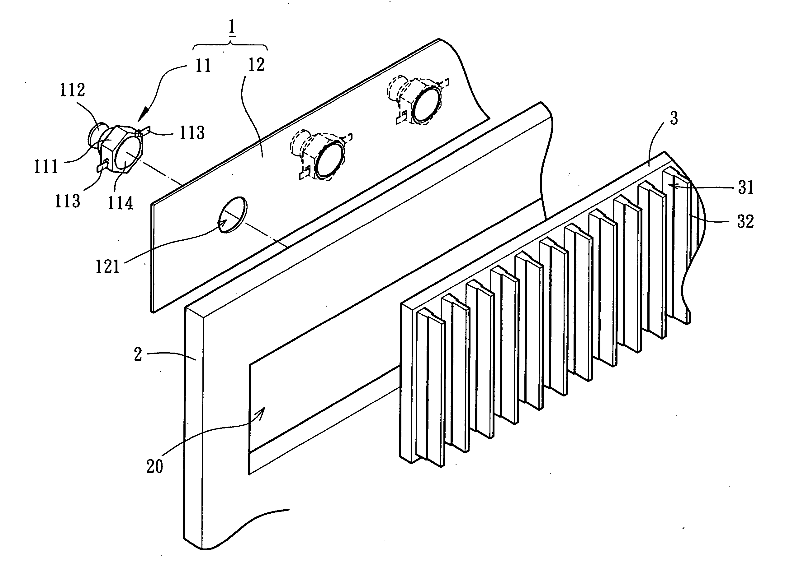
[0036]Referring to FIGS. 2 and 3, the first embodiment of the heat-dissipating device for a back light source for a flat panel display in accordance with the present invention comprises at least one back light module 1, a support frame 2, and at least one heat-dissipating board 3. The back light module 1 and the support frame 2 are in intimate contact with a rear side of the heat-dissipating board 3 for carrying out heat dissipation for the flat panel display “a”. The back light module 1 includes at least one back light unit 11 and a circuit board 12 electrically connected to the back light unit 11....

second embodiment

[0043]FIGS. 7 and 8 illustrate the heat-dissipating device for a back light source for a flat panel display in accordance with the present invention. In this embodiment, the circuit board 12 is directly formed on the rear side of the heat-dissipating board 3 and includes at least one assembling hole 121. The thermally conductive portion 114 of the associated back light unit 11 is extended through the assembling hole 121 and in contact with the rear side of the heat-dissipating board 3, thereby effectively enhancing the heat-dissipating efficiency.

[0044]In the first embodiment or the second embodiment, when the back light unit 11 is in contact with the rear side of the heat-dissipating board 3 via the assembling hole 121, a layer of welding flux (not shown) can be provided in advance on an engaging side of the thermally conductive portion 114 that is engaged with the heat-dissipating board 3. The layer of welding flux can be heated and molten by surface mount technology (SMT), thereb...


PUM


Abstract

A heat-dissipating device for a back light source for a flat panel display includes at least one back light unit, a circuit board, and at least one heat-dissipating board. The back light unit includes a lighting element and a thermally conductive portion connected thereto for absorbing heat generated by the lighting element. The circuit board includes at least one assembling hole and is electrically connected to the back light unit to form a back light module. The heat-dissipating board is mounted to a rear side of the heat-dissipating board. The thermally conductive portion of the back light unit is extended through the assembling hole of the circuit and directly in contact with the rear side of the heat-dissipating board, allowing the heat-dissipating board to absorb and thus dissipate the heat generated by the back light module.

Description

BACKGROUND OF THE INVENTION[0001]1. Field of the Invention[0002]The present invention relates to a heat-dissipating device and, more particularly, to a heat-dissipating device for a back light source for a flat panel display.[0003]2. Description of Related Art[0004]FIG. 1 illustrates a conventional heat-dissipating device for a back light source for a flat panel display. The device comprises a plurality of back light units 6, a circuit board 7, a support frame 8, and a heat-dissipating board 9. The back light units 6 are mounted to a side of the circuit board 7. The back light units 6 are electrically connected to the circuit board 7 such that the circuit board 7 may control the back light units 6 to provide a back light source. Each back light unit 6 includes a base 61, a lighting element 62, and at least two pole plates 63. The base 61 includes a compartment for receiving and positioning the lighting element 62 and the pole plates 63. The lighting element 62 is a light-emitting di...

Claims


Application Information

Patent Timeline
Patent Type & Authority Applications(United States)
IPC IPC(8): H05K7/20
CPCG02F2001/133628G02F1/133603H05K7/20972G02F1/133628
Inventor HORNG, ALEXTE-CHEN, LIU
Owner SUNONWEALTH ELECTRIC MACHINE IND
Why Eureka
Try Eureka