Concrete finishing machine

Active Publication Date: 2008-03-20
FABCON
View PDF30 Cites 0 Cited by
  • Summary
  • Abstract
  • Description
  • Claims
  • Application Information

AI Technical Summary

Benefits of technology

[0010]It is also very desirable in either system to be able to accurately and easy imprint the upper surface of the still uncured concrete with a variety of patterns, such as a simulated brick or raked lines for surface decorations. Tying in with the CAD drawings and the position of the bed with a concrete finishing machine ensures that imprinted patterning may be accurately made with a minimum of cost and personnel.
[0011]This disclosure shows an automated system for casting concrete panels which takes CAD drawings for a casting bed that covers the features throughout the length of the bed and accurately projects a laser generated image of the drawings over the bed at the exact location corresponding to the CAD drawings. This e

Problems solved by technology

Prior art approaches have used hand laid

Method used


Image

  • Concrete finishing machine
  • Concrete finishing machine
  • Concrete finishing machine

Examples


Example

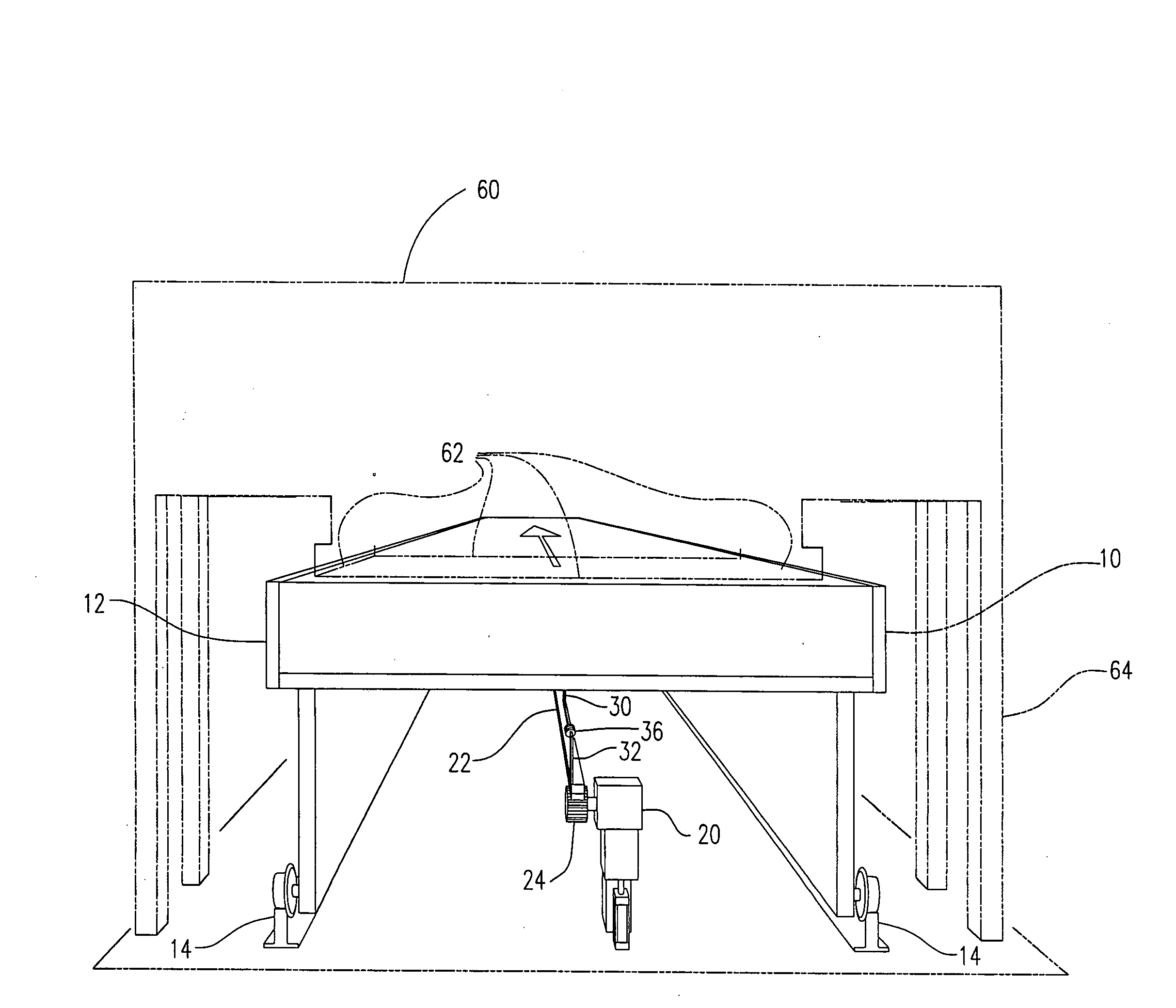
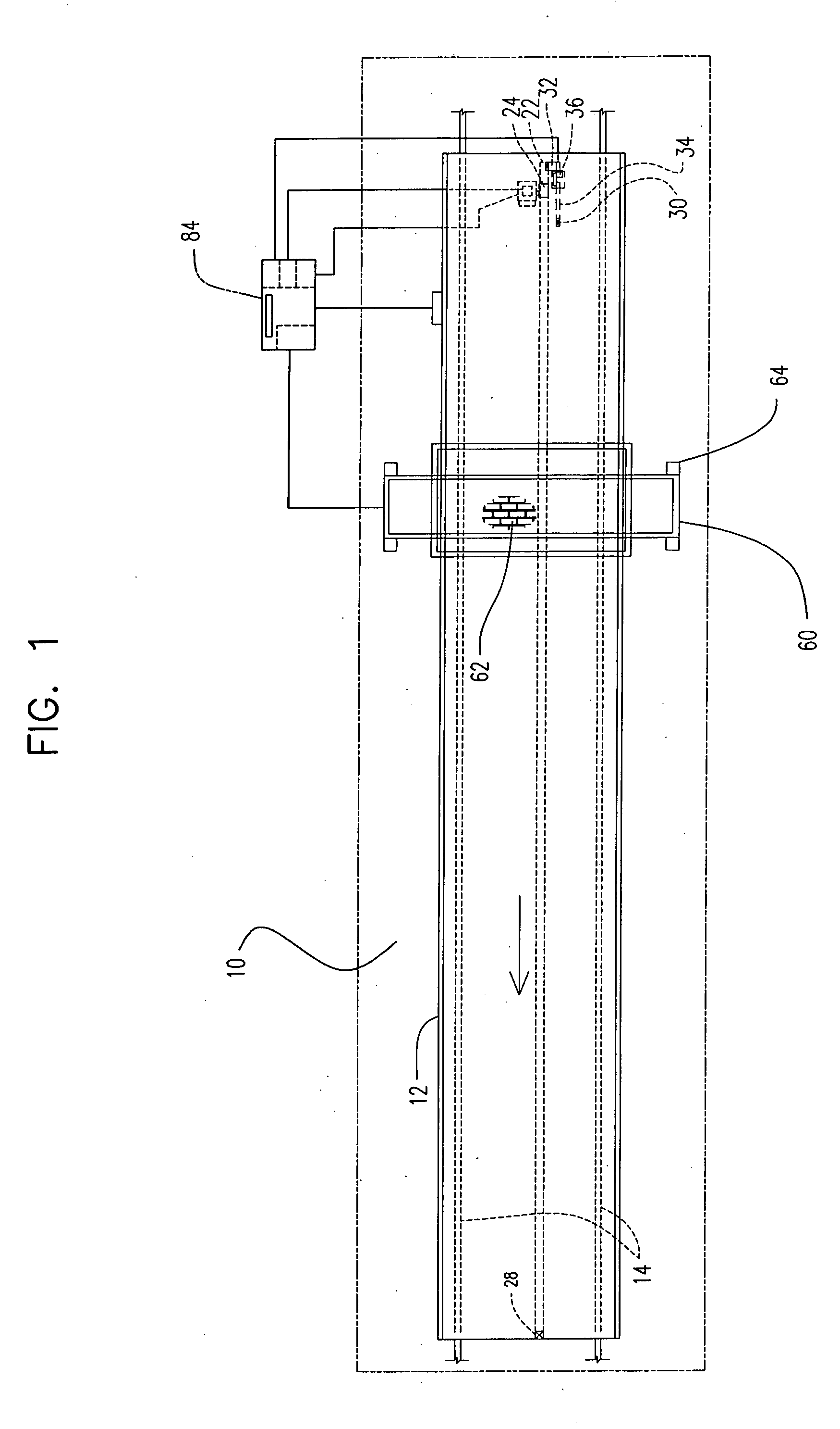
[0024]With reference to FIG. 1, the form of the finishing machine used in connection with a moving casting bed 10 is employed is shown. Moving casting beds 10 are well known in the art, and typically include a concrete form 12 that may be 900 feet long. The bed 10 has tracks 14 that ride on rails such that the entire bed 10 may be moved down the rails. This allows the bed 10 to be moved to each of the fixed stations, such as for pouring concrete on the bed from an overhead hopper.

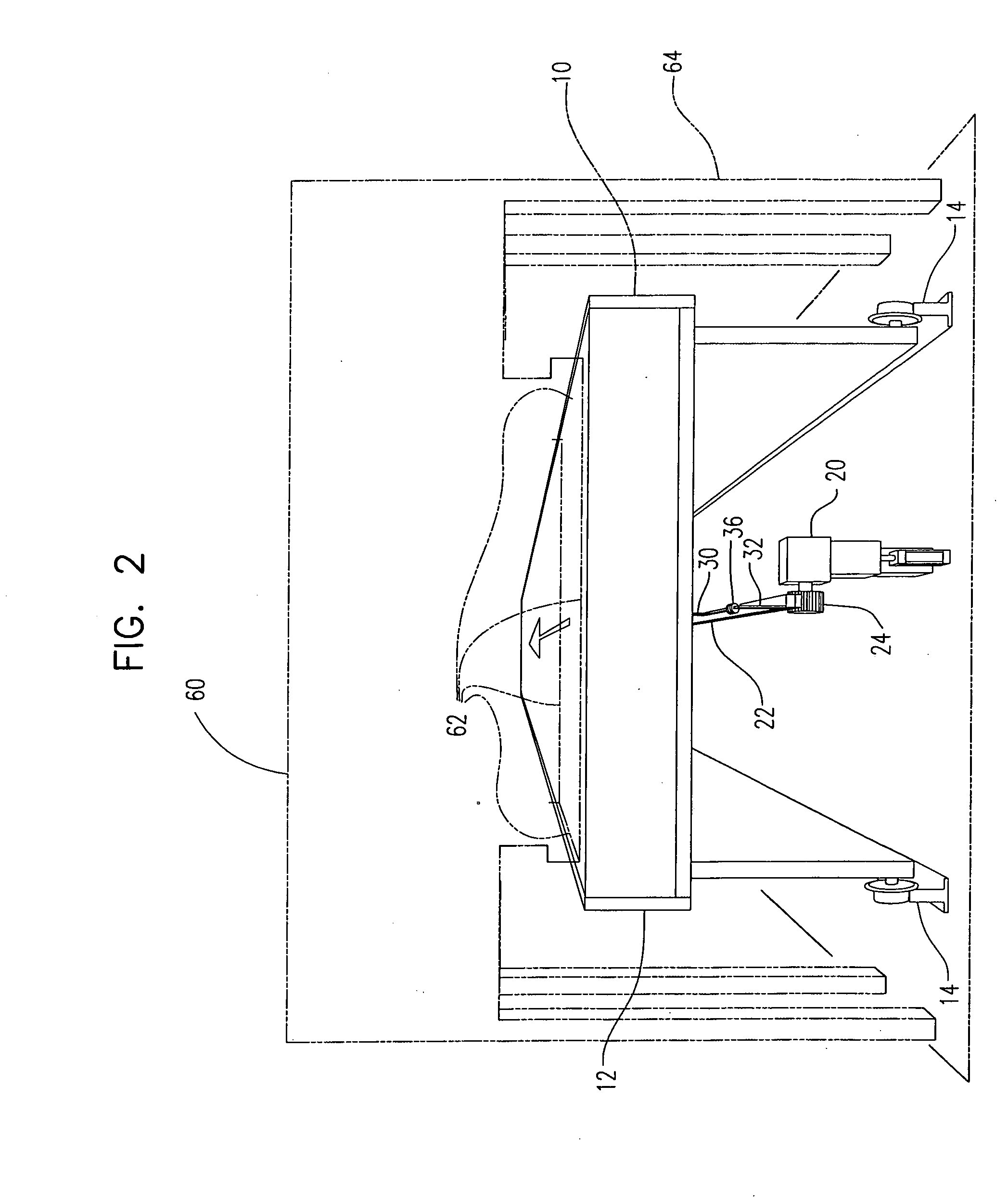
[0025]The underside of a typical casting bed 10 is shown in FIGS. 2-4 in which it will be seen that a mechanism to precisely indicate the exact position on the bed 10 may be generated. The bed position device 20 is used to provide a signal that indicates the exact position of the bed to a known position in the plant. As shown, it involves the addition of a rack 22 to the underside of the casting bed 10. The rack 22 engages with a pinion 24 which is attached to an encoder 26. The rack 22 has a fixed rack anc...


PUM

PropertyMeasurementUnit
Lengthaaaaaaaaaa
Heightaaaaaaaaaa

Abstract

A machine for imprinting patterns onto uncured concrete in an elongated bed includes a frame for positioning the finishing machine over the bed. A lower patterning unit suspended from the frame is movable backward and forward of the concrete bed and a press assembly moves the pattern in and out of contact with uncured concrete on the elongated bed.

Description

CROSS-REFERENCE TO RELATED APPLICATIONS[0001]None.STATEMENT REGARDING FEDERALLY SPONSORED RESEARCH OR DEVELOPMENT[0002]Not Applicable.BACKGROUND OF THE INVENTION[0003]This invention relates to a concrete finishing machine for use in concrete casting system. Such casting systems typically have either a moving bed or a fixed bed on which the concrete panels or planks are formed. In the moving bed systems, a long bed moves on a track past each of the various stations that form the panels. See for example, U.S. Pat. No. 4,369,153. In a fixed bed, the various stations themselves move, such as a hopper that pours concrete onto the bed.[0004]Prior art approaches have used hand laid patterns which are very labor intensive. Very simple longitudinal ribbing is relatively easy to accomplish as shown in U.S. Pat. No. 4,457,682. Brick imprinting on surfaces has been tried with a number of different approaches, including U.S. Pat. No. 5,318,426 which is commonly owned, the disclosure of which is ...

Claims


Application Information

Patent Timeline
IPC IPC(8): B29C67/00
CPCB28B17/0081B28B11/08
Inventor LEJEUNE, MICHAELWESEN, RICHARDMORFORD, GREGORYHEMAN, PATRICKYZERMANS, MARKHENDERSON, DAVIDHENSLEY, JASONKUCKHAHN, THOMAS
Owner FABCON
Why Eureka
Try Eureka