Sensor network system and sensor node

a sensor network and sensor node technology, applied in power management, sustainable buildings, high-level techniques, etc., can solve the problems of increasing hardware costs, increasing the difficulty of technique, and unable to guarantee that data addressed to the sensor will actually be generated at that time, so as to improve the response performance, reduce power consumption, and prolong sleep time

Inactive Publication Date: 2008-03-20
HITACHI LTD
View PDF5 Cites 74 Cited by
  • Summary
  • Abstract
  • Description
  • Claims
  • Application Information

AI Technical Summary

Benefits of technology

[0015]Therefore, the present invention can simultaneously enhance the response performance when plural data is transmitted to

Problems solved by technology

This leads to increased difficulty of technique, or to increased cost of hardware.
Since data addressed to a receiving station (for example, a command which instructs instant execution of sensing) may generate any timing for the sake of convenience of an application user and a system manager, even if the data transmission timing on the next occasion is specified, there is no guarantee that data addressed to the sensor will actually be generated at that time.
Therefore, data is not neces

Method used


Image

  • Sensor network system and sensor node
  • Sensor network system and sensor node
  • Sensor network system and sensor node

Examples


Embodiment Construction

[0030]One embodiment of the invention will now be described referring to the attached drawings.

FIG. 4: Overall View of System

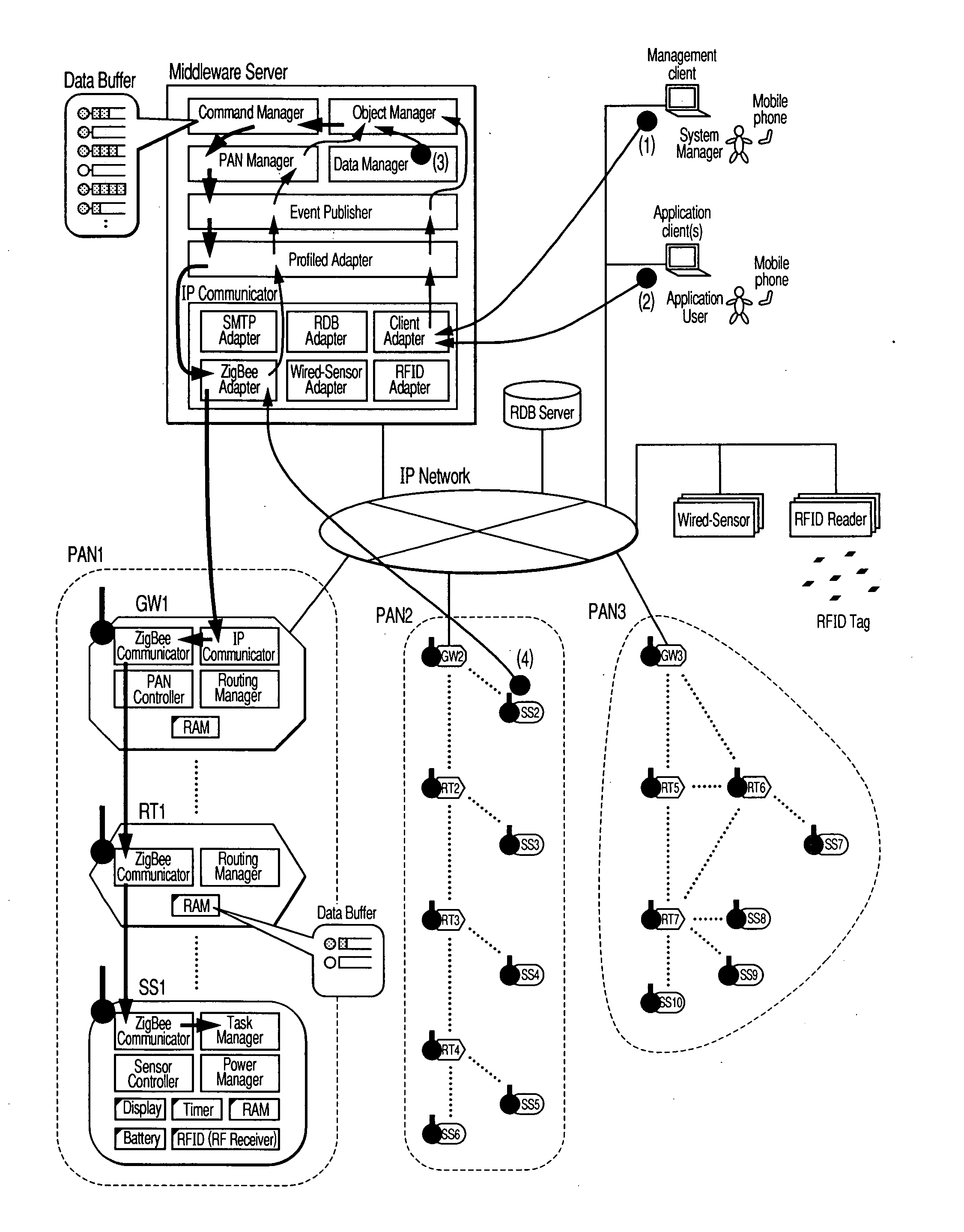
[0031]FIG. 4 is an overall schematic view showing an example of a sensor network system which is a major application of the invention. Examples of industrial application of the invention are air-conditioning management of a whole building, monitoring of manufacturing steps in a factory, detection of toxic gases or fires, or noise management around trunk roads or factory sites.

FIG. 5: Sensor Node SS1

[0032]FIG. 5 is a view showing a modification of the hardware of the sensor node SS1. The battery is a device for supplying power to each hardware unit of the sensor node SS1. A self-power generation device like an ordinary primary cell, a rechargeable battery which can be charged, a solar cell or an oscillating generator, can be used.

[0033]A MicroProcessor controls the overall operation of the sensor node SS1. By reading and executing a program code from the ROM Re...


PUM


Abstract

A plural-data transmission Start message is transmitted prior to transmission of plural data to an intermittent operation type wireless communications terminal, and when transmission of plural data is completed, a plural-data transmission End message is transmitted. The terminal which received the plural-data transmission Start message can change over the sleep period of the aforesaid intermittent operation to a shorter sleep period. Thereby, an improvement in the response performance in the case of plural-data delivery can be simultaneously obtained while maintaining the low power performance of a sensor node.

Description

CLAIM OF PRIORITY[0001]The present application claims priority from Japanese application JP 2006-248874 filed on Sep. 14, 2006, the content of which is hereby incorporated by reference into this application.FIELD OF THE INVENTION[0002]The present invention relates to a compact low power wireless terminal, and in particular, to a bidirectional data transmission technology in a sensor node forming a sensor network.BACKGROUND OF THE INVENTION[0003]A sensor network is a technology which has rapidly been attracting attention in recent years. By applying sensor network technology, sensing of information relating to the real world is performed in semi-real time, and this can be incorporated into an IT system as electronic information. Various applications are now being devised, and are expected to become next-generation IT techniques to support the coming ubiquitous society.[0004]A key device in a sensor network is a wireless sensor node characterized by its compactness and low power consu...

Claims


Application Information

Patent Timeline
IPC IPC(8): H04Q7/20H04W52/02H04W84/12
CPCY02B60/50H04W52/0216Y02D30/70
Inventor OGUSHI, MINORUMURO, KEIROODAKA, TOSHIYUKISUZUKI, KEISUZUKI, SHOJI
Owner HITACHI LTD
Why Eureka
Try Eureka