Implant

a joint and implant technology, applied in the field of implants, can solve the problems of unsatisfactory effects in the body, the wear of hip implants is usually about 30 m, and the accuracy of the joint is not high, and achieves the effect of high accuracy and easy attainment of desired properties

Inactive Publication Date: 2008-03-20
UNIV DUISBRG ESSEN +1
View PDF5 Cites 67 Cited by
  • Summary
  • Abstract
  • Description
  • Claims
  • Application Information

AI Technical Summary

Benefits of technology

[0013] An object of the present invention is to provide an implant with a micro-rough bearing surface and a method for producing such an implant, wherein the implant can be produced easily with high accuracy and / or with the desired properties so that wear and the generation of debris can be minimized.

Problems solved by technology

Wear debris is of concern because it causes, inter alia, osteolysis and may lead to undesired effects in a body in which the implant is implanted.
However, such a hip implant usually has a wear of about 30 μm during the starting phase of use (“running in”) and of about 5 μm in the following years.
The etching results in that the surface shape or dimensions are altered so that it is very difficult to achieve a desired, pre-determined geometry of the bearing surface with high accuracy.

Method used


Image

  • Implant
  • Implant
  • Implant

Examples


Embodiment Construction

[0029] For the purposes of promoting an understanding of the disclosure, reference will now be made to the embodiments illustrated in the drawings and specific language will be used to describe the same. It will nevertheless be understood that no limitation of the scope of the disclosure is thereby intended, such alterations and further modifications in the illustrated device and its use, and such further applications of the principles of the disclosure as illustrated therein being contemplated as would normally occur to one skilled in the art to which the disclosure relates.

[0030] In the figures, the same designations are used for identical or similar parts, corresponding or comparable advantages and properties being achieved even if the description is not repeated for reasons of simplification.

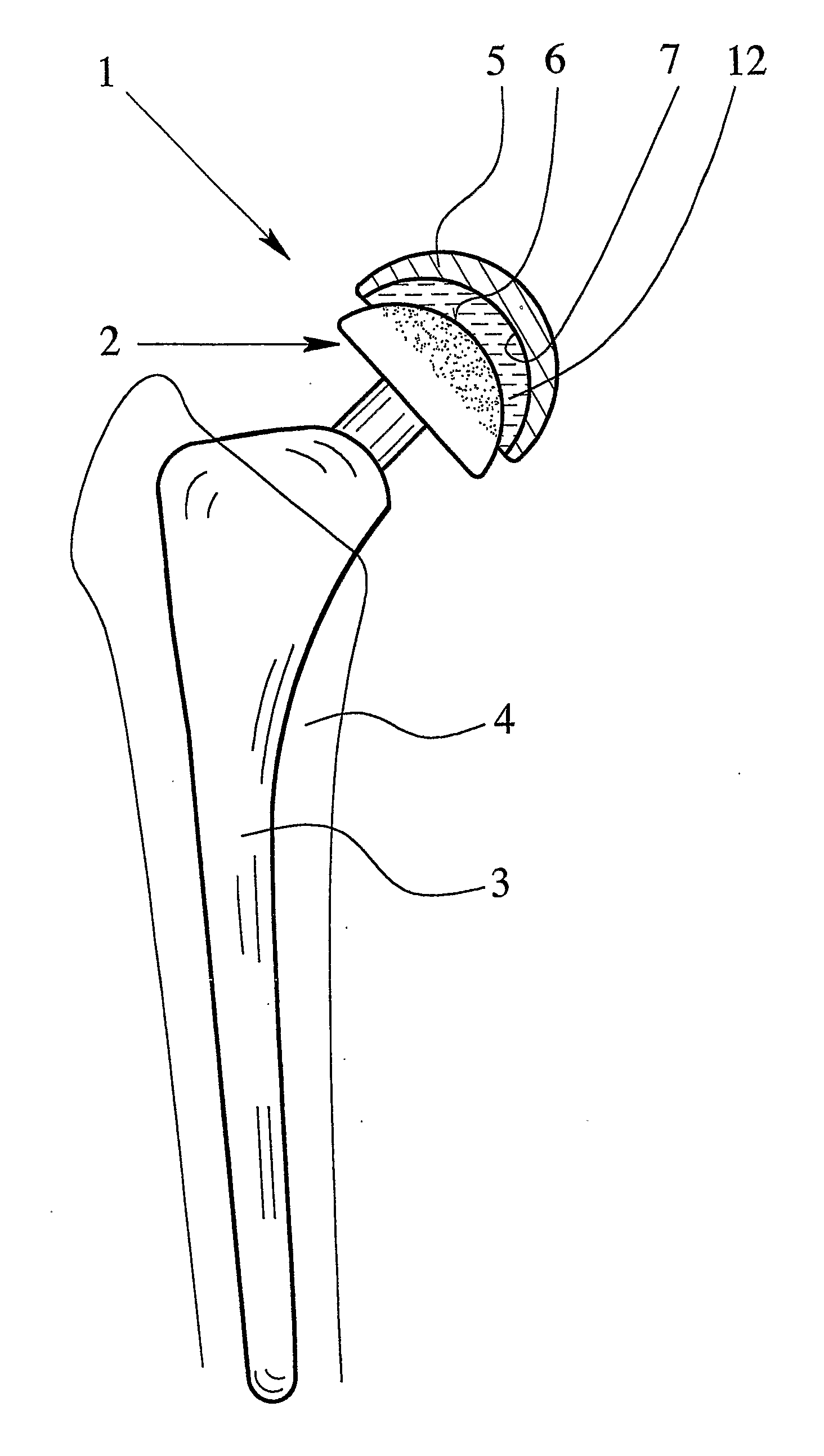
[0031]FIG. 1 shows in a schematic representation an embodiment of an orthopedic implant 1 according to the present invention. In case of the example represented, the implant 1 forms a join...


PUM

PropertyMeasurementUnit
porosityaaaaaaaaaa
porosityaaaaaaaaaa
porosityaaaaaaaaaa

Abstract

An implant and method for producing an implant are disclosed. The implant forms a joint with a micro-rough bearing surface formed by a sintered portion. Thus, better wear and friction properties can be achieved.

Description

CROSS REFERENCES TO RELATED APPLICATIONS [0001] This application is a National Stage filing of International Application PCT / EP2004 / 007929, filed Jul. 16, 2004, entitled “IMPLANT” This reference is expressly incorporated by reference herein, in its entirety.BACKGROUND OF THE INVENTION [0002] 1. Field of the Invention [0003] The present invention relates to an implant forming a joint, such as a hip or knee joint, with a bearing surface for a smooth counter-bearing surface, and to a method for producing such an implant. [0004] 2. Description of Related Art [0005] The invention is directed towards a reduced emission of wear debris from implants forming a joint and, thus, comprising a bearing surface. Wear debris is of concern because it causes, inter alia, osteolysis and may lead to undesired effects in a body in which the implant is implanted. [0006] So-called metal-on-metal prostheses are currently manufactured with a minimum surface roughness, in order to minimize debris. However, s...

Claims


Application Information

Patent Timeline
Patent Type & Authority Applications(United States)
IPC IPC(8): A61F2/30A61F2/32A61F2/62A61F2/00A61F2/34A61F2/36A61L27/30A61L27/56
CPCA61F2/30767A61F2310/0058A61F2/34A61F2002/30011A61F2002/30016A61F2002/30321A61F2002/30644A61F2002/30673A61F2002/30685A61F2002/30769A61F2002/30838A61F2002/30934A61F2002/30968A61F2002/3097A61F2002/3611A61F2250/0019A61F2250/0023A61F2250/0025A61F2310/00017A61F2310/00023A61F2310/00029A61F2310/00131A61F2310/00179A61F2/32A61F2002/30639
Inventor BUSCHER, ROBINWIMMER, MARKUS A.
Owner UNIV DUISBRG ESSEN
Why Eureka
Try Eureka