Accurate and timely body fluid analysis

a body fluid analysis and accurate technology, applied in the field of accurate and timely body fluid analysis, can solve the problems of affecting the health of patients, affecting the accuracy of body fluid analysis,

Inactive Publication Date: 2008-03-27
OPTISCAN BIOMEDICAL
View PDF0 Cites 235 Cited by
  • Summary
  • Abstract
  • Description
  • Claims
  • Application Information

AI Technical Summary

Problems solved by technology

Often this is done in a hospital or clinical setting when there is a risk that the levels of certain analytes may move outside a desired range, which in turn can jeopardize the health of a patient.
Certain currently known systems for analyte monitoring in a hospital or clinical setting suffer from various drawbacks.

Method used


Image

  • Accurate and timely body fluid analysis
  • Accurate and timely body fluid analysis
  • Accurate and timely body fluid analysis

Examples


example 1

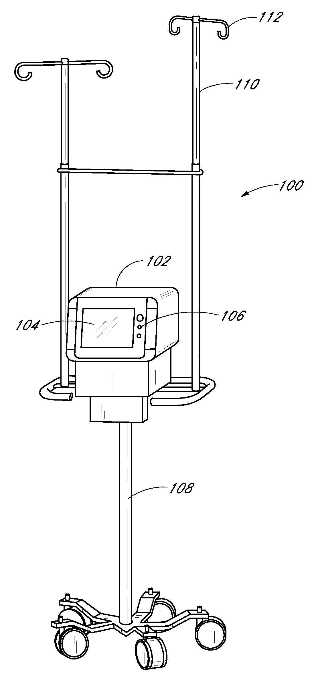
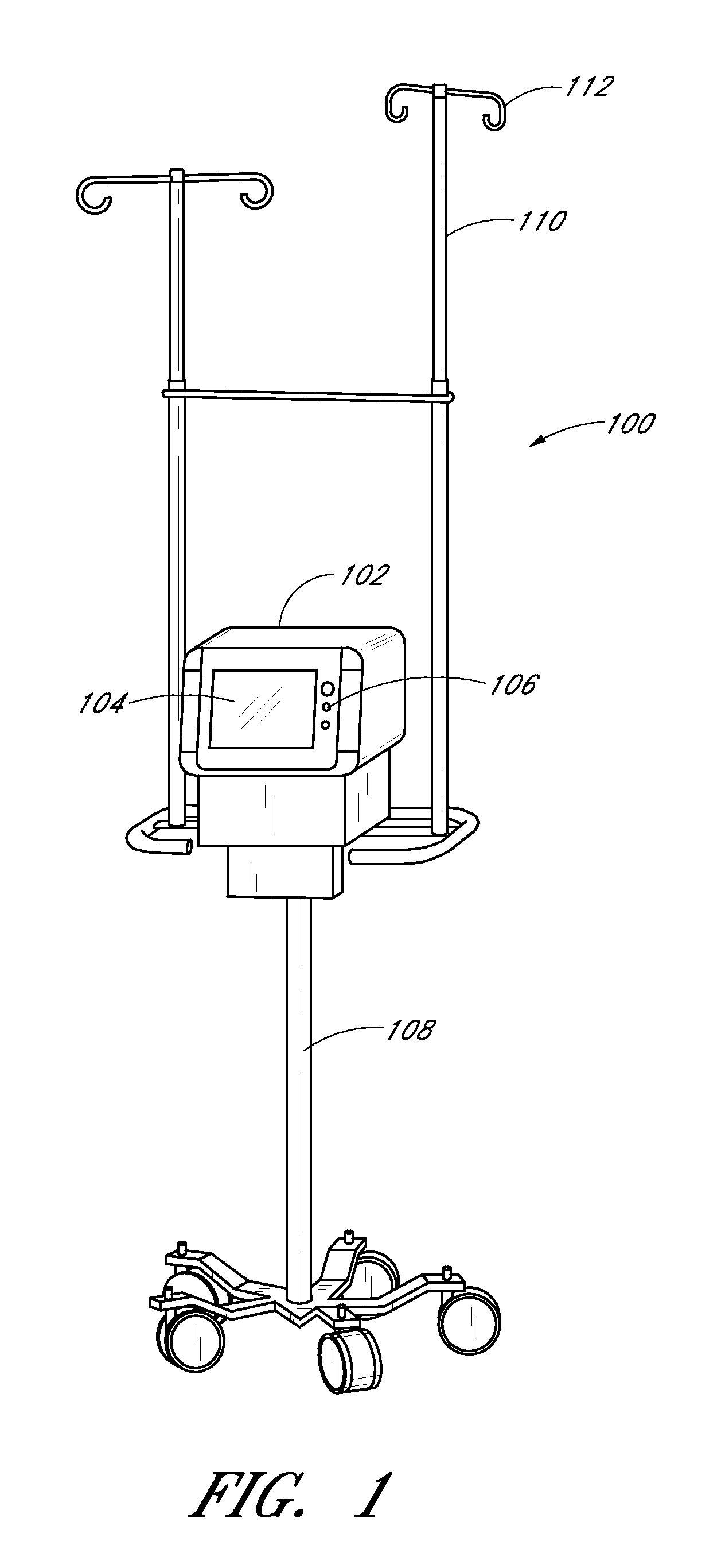
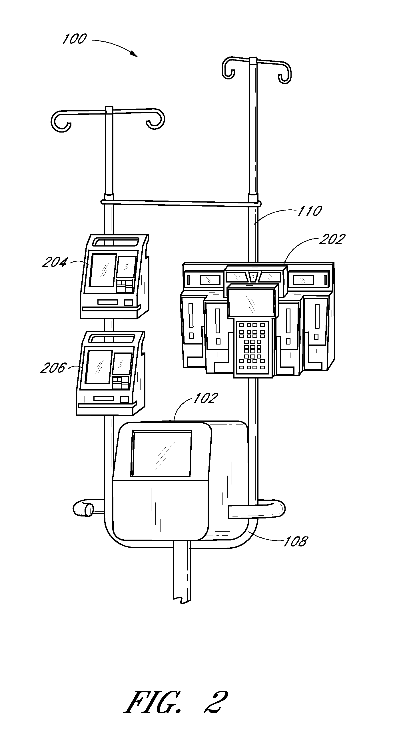
[0218] The sampling system 102 and its components can optionally be embodied as described in the discussion of this Example 1. The sampling system is a reagentless, continuous, point of care analyzer incorporating a Mid Infrared spectroscopic measurement engine and a single patient use centrifugal whole blood separator. Vascular access is made by direct connection to an arterial, central venous or peripheral venous catheter. The instrument automatically makes a plasma glucose measurement every 15 minutes using 40 microliters of whole blood per measurement. When used with a computational algorithm as set forth herein it is very well suited to rejecting the relatively large doses of injectable interferents and wide-ranging endogenous substances commonly found in the critical care setting.

[0219] A study was used to evaluate the baseline accuracy and the performance of Mid IR technology in actual ICU samples.

[0220] The sampling system used in the study includes a pole mounted, point o...

example 2

[0228]FIG. 23 shows a comparison of the results of measurements obtained with the sampling system (“Estimated”) of patients from an ICU at Stamford Hospital in Stamford, Conn. with measurements obtained with laboratory grade analytical equipment (“Reference”) of the Stamford ICU patients. The results show the effectiveness of the Interferent Rejection algorithm described herein on real blood samples, illustrating the standard error for the measurement of glucose, in the presence of interferents, to be 9.75 mg / dL with a spectrometer total integration time of 1 minute.

example 3

Beta Performance Model Predictions

[0229]FIGS. 24, 25, and 26 illustrate the results of calculations showing the trade-off of accuracy and time for a glucose monitoring system. Specifically, FIGS. 24-26 show predictions of the performance of the spectrometer for two important variables, source power and integration time at each filter. The three graphs (labeled Beta900 mW, Beta750 mW, and Beta600 mW) represent three light source power levels (900 mW, 750 mW and 600 mW) for the optical system 1210 (see FIG. 12). The lines on the graphs (labeled Beta, Tint=1; Beta, Tint=2; and Beta, Tint=3, respectively) indicate different integration times for the spectroscopic measurements, and correspond to a total measurement time of 25 seconds, 50 seconds, and 75 seconds, respectively.

[0230] The horizontal axis in each graph of FIGS. 24-26 is standard error in mg / dL, from 2 to 14. The vertical axis has arbitrary units, and is an indicator of the number of samples at each standard error level. Th...


PUM

PropertyMeasurementUnit
concentrationaaaaaaaaaa

Abstract

A method of extracting and analyzing bodily fluids from a patient at the point of care for the patient is provided. The method comprises establishing fluid communication between an analyte detection system and a bodily fluid in the patient. A portion of the bodily fluid is drawn from the patient. A first component of the bodily fluid is separated from the drawn portion, while the analyte detection system remains in fluid communication with the patient. The analyte detection system analyzes the first component to measure a concentration of an analyte in an accurate and timely manner.

Description

PRIORITY INFORMATION [0001] This application claims the benefit under 35 U.S.C. §119(e) of the following U.S. Provisional Patent Application Nos.: 60 / 837,832, filed Aug. 15, 2006 (attorney docket no. 171PR); 60 / 837,746, filed Aug. 15, 2006 (attorney docket no. 172PR); 60 / 901,474, filed Feb. 15, 2007 (attorney docket no. 178PR); 60 / 939,036, filed May 18, 2007 (attorney docket no. 183PR); 60 / 939,023, filed May 18, 2007 (attorney docket no. 184PR); 60 / 950,093, filed Jul. 16, 2007 (attorney docket no. 186PR); and 60 / 953,454, filed Aug. 1, 2007 (attorney docket no. 190PR). The entirety of each of the above-referenced applications is hereby incorporated by reference and made part of this specification.BACKGROUND [0002] 1. Field [0003] Certain embodiments disclosed herein relate to methods and apparatus for determining the concentration of an analyte in a sample, such as an analyte in a sample of bodily fluid, as well as methods and apparatus which can be used to support the making of such...

Claims


Application Information

Patent Timeline
Patent Type & Authority Applications(United States)
IPC IPC(8): G01N33/00B01J19/00B04B5/10
CPCA61B5/1427G01N21/35A61B5/14557A61M1/3621A61M5/14A61M5/1415A61M2005/1404A61M2005/1726A61M2230/201B01L3/502B01L2200/10B01L2300/0816B01L2400/0478B01L2400/0633G01N35/1095B01L3/50273B01L3/52A61B5/14532A61B5/15003A61B5/150221A61B5/150229A61B5/150236A61B5/150244A61B5/150267A61B5/150305A61B5/150755A61B5/150786A61B5/150824A61B5/153A61B5/157A61M1/362266A61M1/36226A61M1/362227A61M1/36222A61M1/36225
Inventor KEENAN, RICHARDCHIOU, JEFFREYTONG, ROGERRECKNOR, MICHAELLI, KEN I.BRAIG, JAMES R.CALLICOAT, DAVID N.GABLE, JENNIFER H.
Owner OPTISCAN BIOMEDICAL
Why Eureka
Try Eureka