Plasma Nozzle Array for Providing Uniform Scalable Microwave Plasma Generation

a plasma nozzle array and microwave plasma technology, applied in plasma technology, energy-based chemical/physical/physico-chemical processes, disinfection, etc., can solve the problems of one or more plasma species temperatures, high cost of operation, thermal sensitivity and destruction

Inactive Publication Date: 2008-03-27
SAIAN CORP +1
View PDF13 Cites 28 Cited by
  • Summary
  • Abstract
  • Description
  • Claims
  • Application Information

AI Technical Summary

Benefits of technology

[0023] These and other advantages and features of the invention will become apparent to those persons skilled in the art upon reading the details of the invention as more fully described below.

Problems solved by technology

A low plasma pressure, on the other hand, may yield one or more temperatures for the plasma species due to insufficient collisions between the species of the plasma.
These technologies have a number of problems that must be dealt with and overcome and these include issues such as thermal sensitivity and destruction by heat, the formation of toxic byproducts, the high cost of operation, and the inefficiencies in the overall cycle duration.
Consequently, healthcare agencies and industries have long needed a sterilizing technique that could function near room temperature and with much shorter times without inducing structural damage to a wide range of medical materials including various heat sensitive electronic components and equipment.
The most of these designs are single nozzle based and they lack large volume scalability required for sterilization of medical devices applications.
Also, such plasma systems generate high temperature plasma, which is not suitable for sterilization applications.
One of the challenging problems of such a system is controlling the microwave distribution within the microwave cavity so that the microwave energy (or, equivalently microwave) is localized at intended regions (hereinafter, referred to as “high-energy regions”) that are stationary within the cavity.

Method used


Image

  • Plasma Nozzle Array for Providing Uniform Scalable Microwave Plasma Generation
  • Plasma Nozzle Array for Providing Uniform Scalable Microwave Plasma Generation
  • Plasma Nozzle Array for Providing Uniform Scalable Microwave Plasma Generation

Examples


embodiment 122

[0061]FIG. 4C is a cross-sectional diagram of an alternative embodiment 122 of the microwave cavity and nozzle array depicted in FIG. 4B. As illustrated, a nozzle 128 has similar components as those shown in FIG. 4B. FIG. 4C includes a gas flow tube 134 sealingly connected to a wall 126 to a receive a gas through a gas flow channel 127; a rod-shaped conductor 130 for collecting microwaves from the high-energy regions 69 in a cavity 133; and a vortex guide 132. The gas flow tube 134 may be made of any material that is substantially transparent to microwaves (i.e., microwaves can pass through the gas flow tube 134 with very low loss of energy) and, as a consequence, the gas flowing through the gas flow tube 134 may be pre-heated within the cavity 133 prior to reaching the region of the tapered tip of the rod-shaped conductor 130.

embodiment 140

[0062]FIG. 4D shows a cross-sectional view of another alternative embodiment 140 of the microwave cavity and nozzle array depicted in FIG. 4A. As illustrated, nozzles 144 have components similar to their counterparts in FIG. 4B: a gas flow tube 148 sealingly connected to a wall 143 of a microwave cavity 142 to receive a gas; a rod-shaped conductor 152 for collecting microwaves from the high-energy regions 69; and a vortex guide 146. The microwave cavity 142 may form a gas flow channel connected to the gas tank 34. The rod-shaped conductor 152 may be similar to the conductor 114 illustrated in FIG. 4B where the portion 116 of the rod-shaped conductor 114 is inserted into the cavity 113 to receive microwaves. Then, the received microwaves travel along the surface thereof and are focused on the tapered tip.

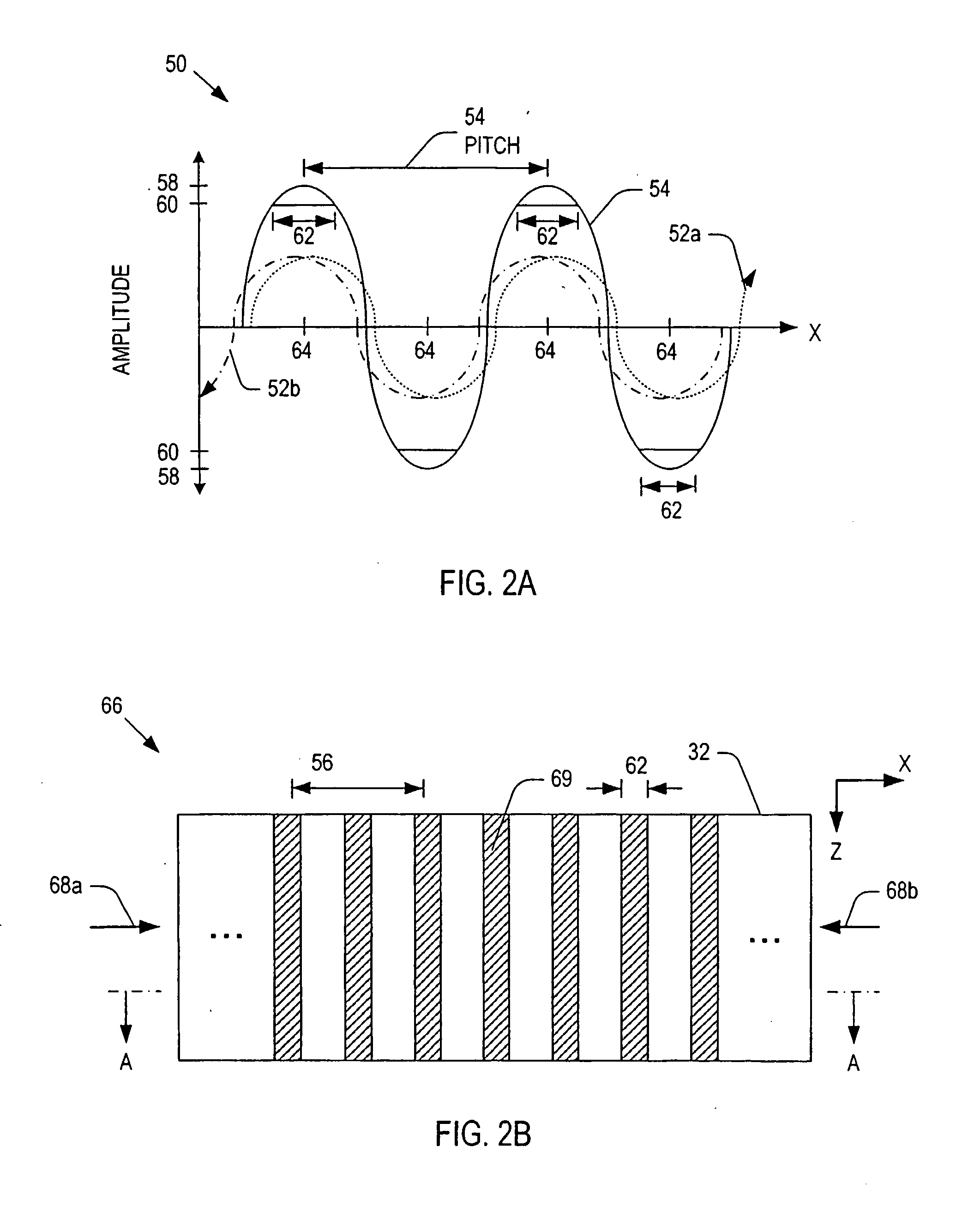
[0063] A mentioned previously, the width 62 (FIG. 2) of the high-energy regions 69 may be optimized by controlling the non-rotating phase shifters 24a and 24b. In general, a smaller ...


PUM


Abstract

The present invention provides microwave plasma nozzle array systems (10, 70, 230, and 310) and methods for configuring microwave plasma nozzle arrays (37, 99, and 337). The microwaves are transmitted to a microwave cavity (323) in a specific manner and form an interference pattern (66) that includes high-energy regions (69) within the microwave cavity (32). The high-energy regions (69) are controlled by the phases and the wavelengths of the microwaves. A plurality of nozzle elements (36) is provided in the array (37). Each of the nozzle elements (36) has a portion (116) partially disposed in the microwave cavity (32) and receives a gas for passing therethrough. The nozzle elements (36) receive microwave energy from one of the high-energy regions (69). Each of the nozzle elements (36) includes a rod-shaped conductor (114) having a tip (117) that focuses on the microwaves and a plasma (38) is then generated using the received gas.

Description

CROSS REFERENCE TO RELATED APPLICATIONS [0001] This application is related to a concurrently filed PCT application Ser. No. ______, filed on Jul. 21, 2005, entitled “SYSTEM AND METHOD FOR CONTROLLING A POWER DISTRIBUTION WITHIN A MICROWAVE CAVITY” which is hereby incorporated by reference in its entirety.BACKGROUND OF THE INVENTION [0002] 1. Field of the Invention [0003] The present invention relates to plasma generating systems, and more particularly to microwave plasma systems having plasma nozzle arrays. [0004] 2. Discussion of the Related Art [0005] In recent years, the progress on producing plasma has been increasing. Typically, plasma consists of positive charged ions, neutral species and electrons. In general, plasmas may be subdivided into two categories: thermal equilibrium and thermal non-equilibrium plasmas. Thermal equilibrium implies that the temperature of all species including positive charged ions, neutral species, and electrons, is the same. [0006] Plasmas may also ...

Claims


Application Information

Patent Timeline
Patent Type & Authority Applications(United States)
IPC IPC(8): H05H1/46H01J37/32
CPCA61L2/14H05H1/46H05H1/24H01J37/32192H05H1/4622H01J37/32229
Inventor LEE, SANG HUNKIM, JAY JOONGSOO
Owner SAIAN CORP
Why Eureka
Try Eureka