Valve assembly with magnetically coupled actuator

Inactive Publication Date: 2008-03-27
TARGET ROCK DIV OF CURTISS WRIGHT FLOW CONTROL
View PDF20 Cites 15 Cited by
  • Summary
  • Abstract
  • Description
  • Claims
  • Application Information

AI Technical Summary

Benefits of technology

[0009]It is desirable to provide a valve that does not require packing and eliminates maintenance and other troubles associated with leakage of external dynamic seals in a valve assembly. It is further desirable to provide a valve having a completely hermetically sealed outer housing that does not have any through openings to reduce or prevent leakage to the outer environment of fluid flowing th

Problems solved by technology

However, a problem with this prior design is that it requires constant maintenance of the packing to prevent fluid leakage.
Such valves are frequently unacceptable due to fluid leakage to the environment, requiring the use of hermetically sealed designs.
However, the problem wi

Method used


Image

  • Valve assembly with magnetically coupled actuator
  • Valve assembly with magnetically coupled actuator
  • Valve assembly with magnetically coupled actuator

Examples


Embodiment Construction

[0023]This invention pertains to a valve assembly that offers exquisite control of the valve disc position, selectively by either manual or motor drive input, while providing a hermetically sealed design.

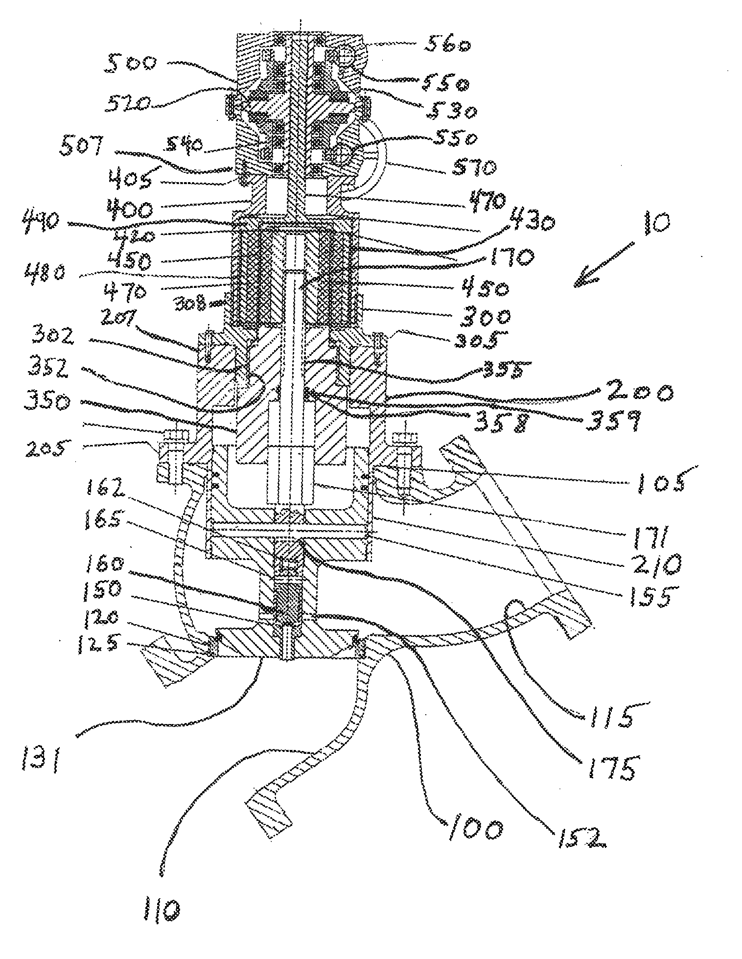
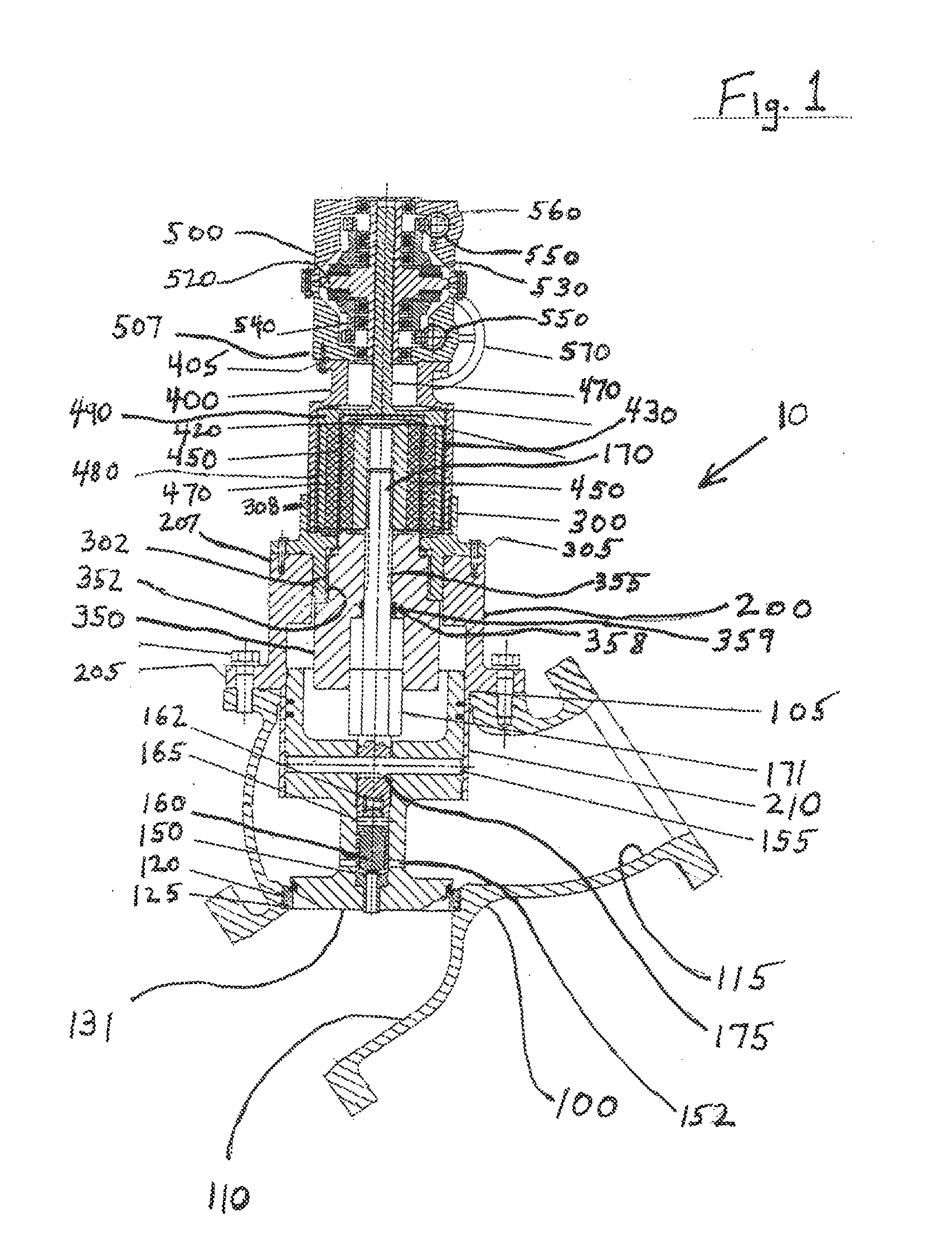
[0024]With reference to the drawings, FIG. 1 shows a piloted globe valve assembly 10. The outer elements of the valve assembly 10 preferably include a valve housing 100, a valve disc collar 200, a bonnet 300, a magnet housing 400 and a gear box 500. It is desirable that the outer elements 100, 200, 300, 400, 500 be secured in such a way as to hermetically seal the overall assembly 10 and prevent either external leakage or internal contamination. As shown, some of the outer elements are provided with coupling flanges 105, 205, 305, 405 or surfaces 207, 507 for securing and sealing adjacent outer elements, using conventional fasteners and seals. Also, some of the outer elements are joined through mating threads 303, 403.

[0025]It should be understood that some or all of the outer eleme...


PUM


Abstract

A valve assembly having a housing including a first and second port. A closure element is disposed within the housing and is selectively moveable between an open position wherein the first port is in fluid communication with the second port and a closed position wherein fluid communication between the first and second ports is blocked and/or controlled. A first magnet assembly is coupled to the closure element for actuating the closure element between the open and closed positions whereby the fluid communication is blocked and/or controlled. A second magnet assembly is magnetically coupled to the first magnet assembly for imparting movement to the first to provide fluid communication blocking and/or controlling. The drive mechanism is adapted to actuate the second magnetic assembly and is alternatively operable through a first and/or a second drive input. The first drive input is unable to drive the second drive input.

Description

BACKGROUND OF THE INVENTION[0001]The invention relates to a sealed fluid valve utilizing a magnetically coupled piloted valve providing a hermetically sealed control valve with improved flow control elements.[0002]Conventional valves have an inlet port and outlet port which are separated by a valve closure element which controls the flow of fluid from the inlet to the outlet. The valve typically has a mechanical movement which moves the closure element from a closed position to an open position. In some prior designs a valve housing is provided having an opening to allow a screw type mechanism to move the closure element from the open to the closed positions and vice versa. Screw mechanisms in these types of valve arrangements would pass through the outer housing of the valve and include a hand wheel or other device to turn the screw mechanism to move the valve between open and closed positions. Such screw mechanisms also include a packing material to provide a dynamic seal between ...

Claims


Application Information

Patent Timeline
IPC IPC(8): F16K31/08
CPCF16K31/086
Inventor LIANTONIO, VITO M.
Owner TARGET ROCK DIV OF CURTISS WRIGHT FLOW CONTROL
Why Eureka
Try Eureka