Image forming apparatus and power supply control method thereof

a technology of image forming apparatus and power supply control, which is applied in the direction of electrographic process apparatus, instruments, optics, etc., can solve the problems of power consumption exceeding energy saving standards, natural discharge of capacitive units, and unattended cooling of fixing units, so as to avoid exceeding energy saving power standards

Inactive Publication Date: 2008-03-27
CANON KK
View PDF2 Cites 17 Cited by
  • Summary
  • Abstract
  • Description
  • Claims
  • Application Information

AI Technical Summary

Benefits of technology

[0032]An object of the present invention, to solve the above problems, is to provide an image forming apparatus and a method of controlling a power supply thereof, that are capable of charging while also avoiding to exceed energy saving power standards that may arise as a result of a projective power consumption in the energy saving standby mode.
[0033]Another object of the present invention is to provide an image forming apparatus and a method of controlling a power supply thereof that are capable of on demand fixing using power stored in the capacitive unit even when the image forming apparatus recovers from the energy saving standby mode, and avoiding a loss in charged power from a natural discharge of the capacitive unit in the energy saving standby mode.
[0034]A further object of the present invention is to provide an image forming apparatus and a method of controlling a power supply thereof that are capable of avoiding the on demand capability being lost as a consequence of recovering from the energy saving standby mode before the charger power level of the capacitive unit has been adequately restored.
[0039]The present invention adds a second charging unit to a conventional first charging unit, and switches over to charging via the second charging unit in energy saving standby mode. As a result, the present invention charges while avoiding exceeding energy saving standards as a consequence of a projective power consumption in the energy saving standby mode. The present invention has an additional benefit of avoiding a loss in charged power from a natural discharge of the capacitive unit in the energy saving standby mode, and facilitating on demand fixing using power stored in the capacitive unit even when the image forming apparatus recovers from the energy saving standby mode.
[0040]With regard to the timing of transitioning to the energy saving standby mode, no transition is made to an energy saving state of a power consumption unit if the first charging unit is in a charge status, and the transition is made to the energy saving state and a switch is made to charging via the second charging unit, at such time as when the charged power level reaches a predetermined power level. It is thus possible to avoid a problem of losing the on demand capability as a consequence of recovering from the energy saving standby mode before the charged power level of the capacitive unit has been adequately restored.

Problems solved by technology

A power supply per Thevenin's theorem is inefficient, however, because it is slow to charge.
While this power consumption is small as average power consumption because of the short duration, the amount of power involved may exceed energy saving standards.
Stopping recharging during the energy saving standby mode, however, causes both a natural discharge of the capacitive unit and a cool down of the fixing unit being left unattended.
In either case, more time is required to recover the image forming apparatus to a print-ready mode, and thereby resulting in a loss of the on demand capability thereof.
Hence, the method in which the charging of the capacitive unit is stopped in the energy saving standby mode fails to maintain the on demand capability.

Method used


Image

  • Image forming apparatus and power supply control method thereof
  • Image forming apparatus and power supply control method thereof
  • Image forming apparatus and power supply control method thereof

Examples


first embodiment

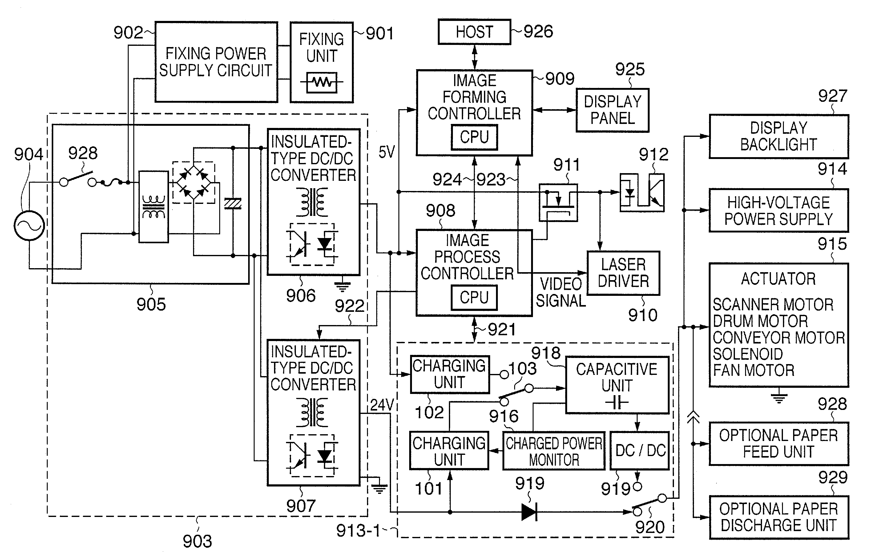
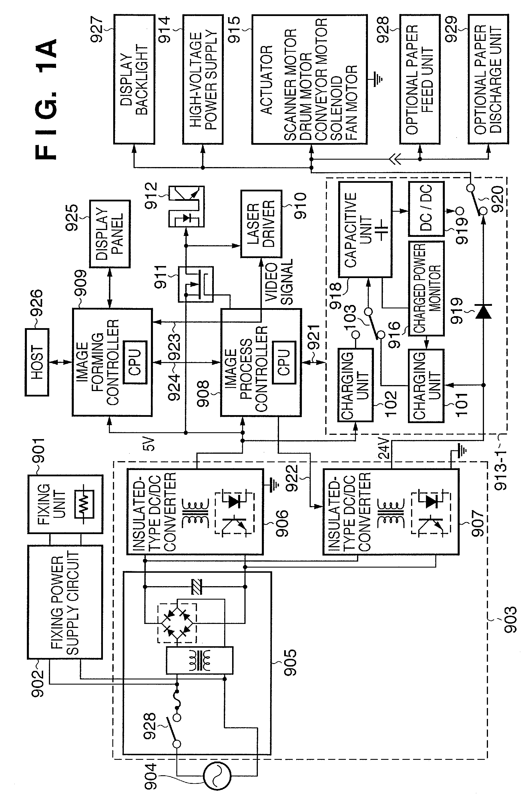
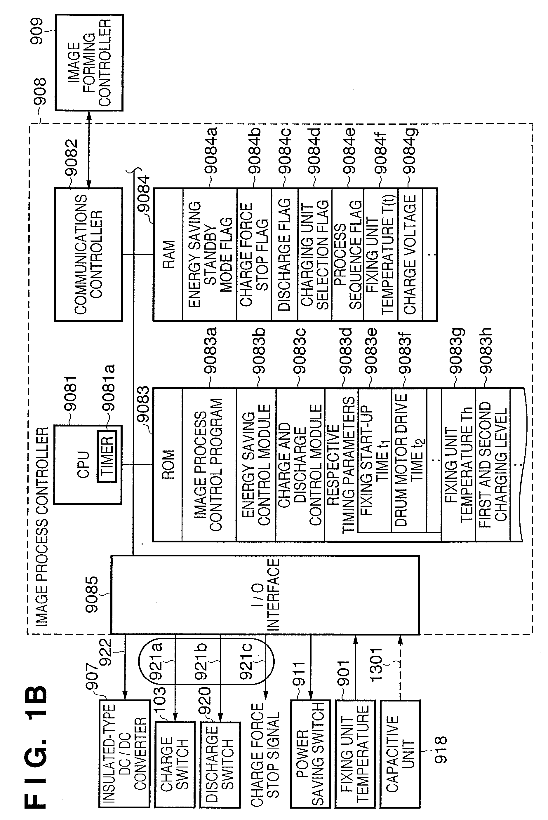
[0061]A first embodiment of the present invention is configured to add a second charging unit to a conventional first charging unit, and to switch over to charging via the second charging unit in energy saving standby mode, by way of providing a unit that reduces power consumption when charging a capacitive unit in energy saving standby mode. In the energy saving standby mode, a backlight in a display panel is dimmed, a power supply for running the display is switched off, a power supply to a paper feed or a paper discharge optional unit is switched off, a power supply for control of such aspects as lighting of a photo interrupter is switched off, an actuator power supply for such purposes as switching off an idle state current of an actuator, including a scanner motor, a solenoid, a stepping motor, a DC motor, and a cooling fan, is itself turned off, a converter that suspends a switching operation of a switching power supply is itself suspended, and / or a clock speed of a controller...

second embodiment

[0091]With regard to a second embodiment, the second charging unit, which reduces power consumption for charging during the energy saving standby mode, is configured by a constant voltage charging circuit to which an AC impedance unit is applied under a chopper control. The second embodiment is characterized by removing a fall in efficiency caused by a current limit resistance, which is a weakness of the constant voltage charge, by switching the charging voltage to change the charging rate of the first charging unit, and thus providing the charging characteristic that is an advantage of the constant voltage charge in a simple configuration.

Example of Configuration of Power Supply Control of Image Forming Apparatus According to Second Embodiment

[0092]FIG. 4 is a conceptual configuration diagram describing a hardware configuration according to the second embodiment. Configurations according to the second embodiment comprising functions identical to configurations according to the firs...

third embodiment

[0102]According to a third embodiment, the second charging unit as the charge power consumption reduction unit in the energy saving standby mode is configured as the constant voltage charge circuit using an external power source such as the commercial power source as the power supply. Thus, the third embodiment allows charging when the switching power supply is off as well as in the energy saving standby mode.

Example of Hardware Configuration of Power Supply Control of Image Forming Apparatus According to the Third Embodiment

[0103]FIG. 6 is a conceptual configuration diagram describing a hardware configuration according to the third embodiment. Configurations depicted in FIG. 6 comprising functions identical to configurations depicted in FIG. 1, according to the first embodiment, and FIG. 4, according to the second embodiment, are designated with identical reference numerals, and descriptions thereof are omitted.

[0104]A power source switch 928 as an on / off unit of the low-voltage po...


PUM


Abstract

An image forming apparatus having a thermal fixing unit reduces a current inputted from a commercial power source using electric power charged in the capacitive when warming up the thermal fixing unit. The apparatus comprises a first charging unit to charge the capacitive unit at a first charging rate, and a second charging unit to charge the capacitive unit at a second charging rate lower than the first charging rate and greater than a natural power discharge rate of the capacitive unit. A charge switching control unit switches a power source charging the capacitive unit from the first charging unit to the second charging unit when the image forming apparatus transitions into an energy saving standby mode, and returns the power source charging the capacitive unit from the second charging unit to the first charging unit when the image forming apparatus returns from the energy saving standby mode.

Description

BACKGROUND OF THE INVENTION[0001]1. Field of the Invention[0002]The present invention relates to an image forming apparatus and a method of controlling a power supply thereof. The image forming apparatus comprises a power storage unit that receives and stores electric power from an external power source such as a commercial power source, and a thermal fixing unit using electrothermally generated temperature. The image forming apparatus reduces usage of electric current from the commercial power source using electric power from both the commercial power source and the power storage unit when the thermal fixing unit is being warmed up. The image forming apparatus, in particular, has an energy saving standby mode, and the present invention relates to energy saving of power storage in the energy saving standby mode.[0003]2. Description of the Related Art[0004]An image forming apparatus is conventionally known, that forms a toner image on a recording medium using an electrophotographic p...

Claims


Application Information

Patent Timeline
Patent Type & Authority Applications(United States)
IPC IPC(8): G03G15/20G03G13/20
CPCG03G15/5004G03G15/2039G03G2215/00983G03G15/80
Inventor MATSUO, SHIMPEI
Owner CANON KK
Why Eureka
Try Eureka