Tool for chip removing machining and a cutting insert therefor

a cutting tool and chip removal technology, applied in the direction of cutting inserts, manufacturing tools, shaping cutters, etc., can solve the problems of chipping and cracks in the peripheral cutting inserts, crack formation at times into drill breakdowns, and the type of indexable insert tools. problems, to achieve the effect of improving the cutting insert, reducing the risk of chipping and crack formation

Active Publication Date: 2008-03-27
SANDVIK INTELLECTUAL PROPERTY AB
View PDF9 Cites 19 Cited by
  • Summary
  • Abstract
  • Description
  • Claims
  • Application Information

AI Technical Summary

Benefits of technology

[0007]The present invention aims at managing the above-mentioned problems and at providing an improved cutting tool and an improved cutting insert therefore. Therefore, a primary object of the invention is to provide a cutting insert suitable for cutting tools, the geometrical design of which is of such a nature that the risk of chippings and tendencies to crack is counteracted efficiently. In this connection, the importance of the desired solution being based on the geometrical design of the cutting insert, rather than on the choice of material of the same, is emphasized. In other words, the drill cutting insert should still be able to be produced from hard, and thereby wear resistant, materials having a long service life, and not from more ductile materials, which, per se, are less inclined to crack.

Problems solved by technology

More precisely, problems have been observed in the type of indexable-insert tools disclosed in International Patent Publication Nos.
The aforementioned problems manifest themselves in that chippings and cracks arise in the peripheral cutting insert, i.e., the cutting insert that afterwards intersects the groove-shaped surface of revolution that already has been generated by the outer part edge of the center insert.
Such crack formation may at times develop into drill breakdowns.
Problems with chipping and crack formation may also be found in other types of cutting tools, in particular rotatable cutting tools, of the type that includes two or more cutting inserts operating in sequence one after the other, the sweep areas of which overlap each other, more precisely in the subsequent cutting insert that, with a certain time delay, intersects a surface already generated by a preceding cutting insert.

Method used


Image

  • Tool for chip removing machining and a cutting insert therefor
  • Tool for chip removing machining and a cutting insert therefor
  • Tool for chip removing machining and a cutting insert therefor

Examples


Embodiment Construction

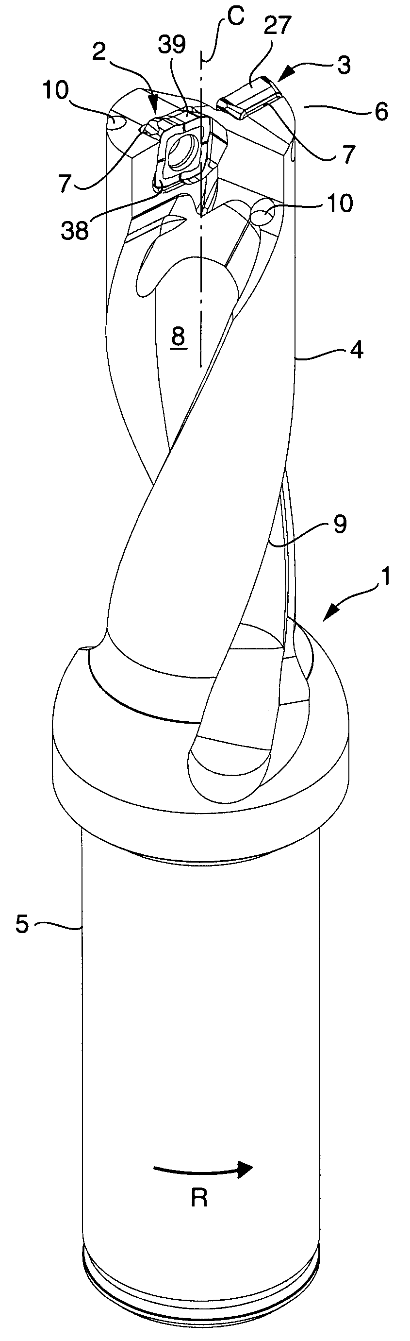
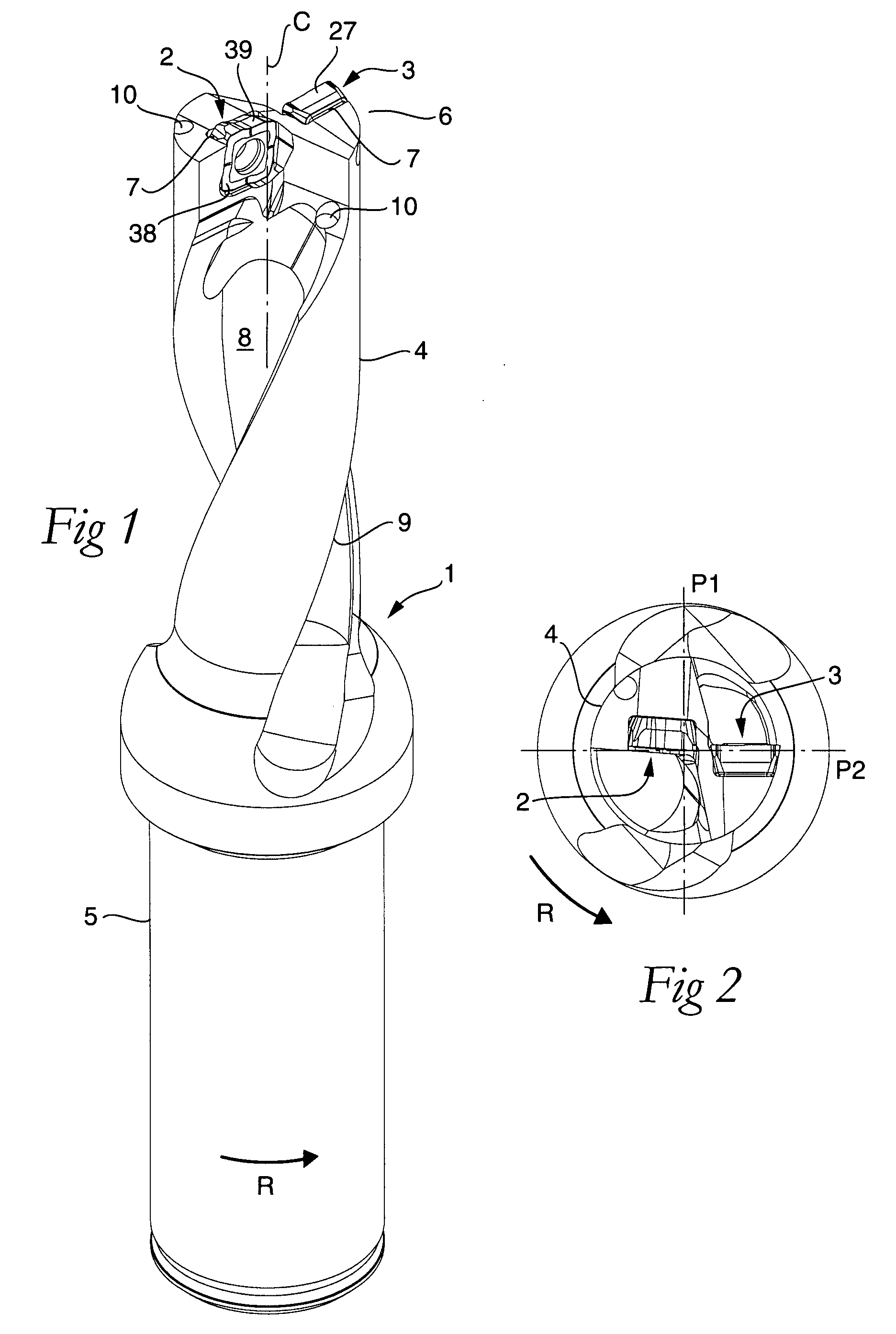
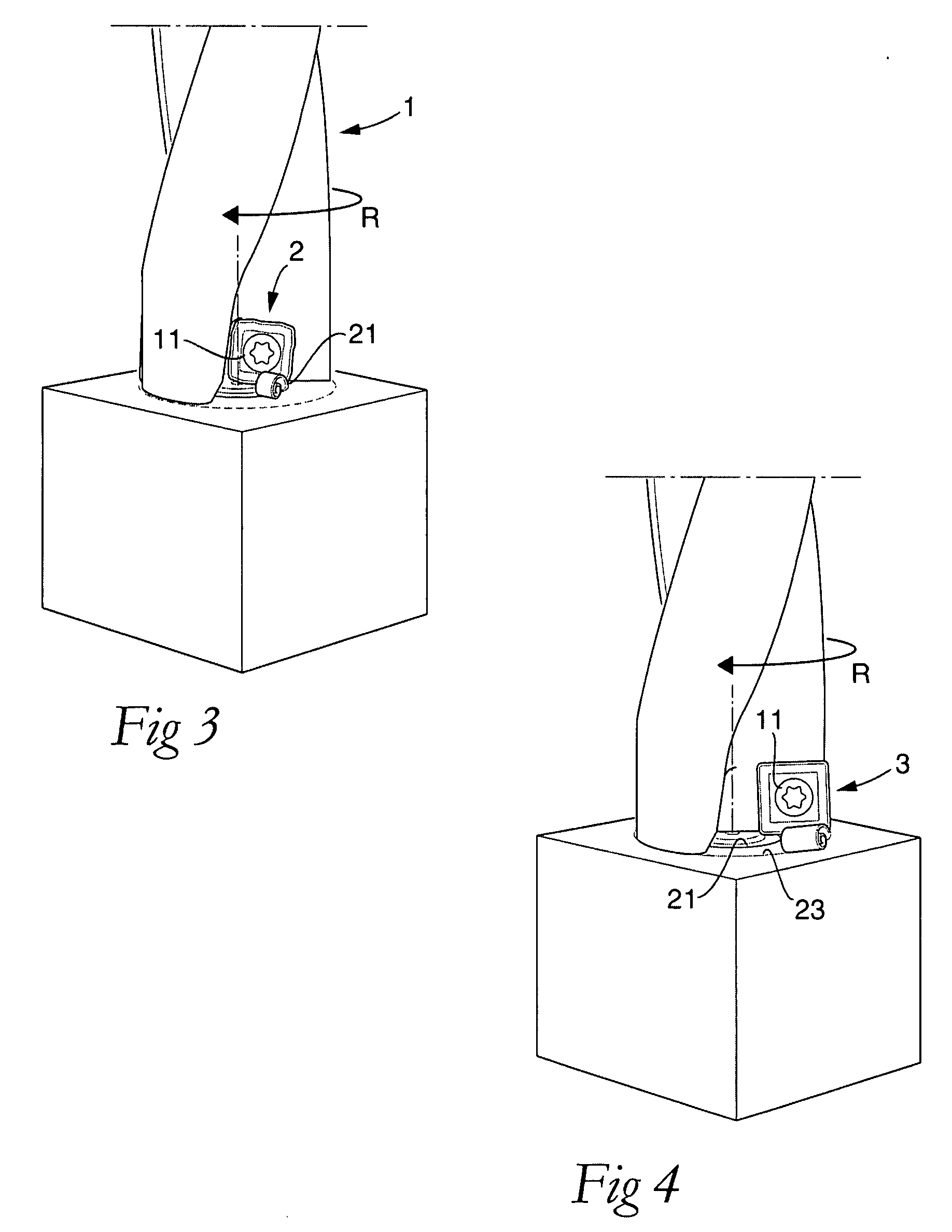
[0025]The tool shown in FIGS. 1 and 2 includes a basic body in the form of a drill body 1, as well as two replaceable cutting inserts, one of which is a center insert 2, and the other a peripheral cutting insert 3. The drill body 1 includes a front part 4 in the form of a shank, as well as a rear part 5, which in this case is thicker than front part 4 and is for mounting in a machine, which can set the tool in rotation. The cutting inserts 2, 3 are arranged at the front end 6 of the drill body. The drill body 1 may be, but does not need to be, solid and manufactured from, for instance, steel, while the cutting inserts 2, 3 are manufactured from a harder and more wear-resistant material, such as cemented carbide.

[0026]Each individual cutting insert is mounted in a pocket 7. Rearward from the individual pocket 7, a chip flute 8 extends, which in this case is helicoidal and delimited by a concavely arched limiting surface. The two chip flutes are situated between two bars 9, the envelo...


PUM

PropertyMeasurementUnit
angleaaaaaaaaaa
angleaaaaaaaaaa
second angleaaaaaaaaaa

Abstract

A tool for chip removing machining, including a basic body and two replaceable cutting inserts. Each insert includes a chip-removing main edge situated between a chip surface and a clearance surface, a first insert of which precedes a second insert during machining of a workpiece. The cutting inserts overlap each other in a zone defined by a borderline along which a surface generated by the main edge of the first cutting insert, with a time delay, is intersected by the main edge of the subsequent, second cutting insert. The main edge of the second cutting insert that afterwards intersects the already generated surface, is formed along a chip surface including primary and secondary sections, which have different shapes in cross-sections spaced-apart along the main edge in order to form a primary part edge and a secondary, reinforced part edge arranged to intersect the already generated surface.

Description

[0001]This application claims priority under 35 U.S.C. § 119 to Sweden Patent Application No. 0602013-5, filed on Sep. 25, 2006, the disclosure of which is incorporated by reference herein in its entirety.FIELD OF THE INVENTION[0002]The present invention relates generally to a cutting tool for chip removing machining of the type that includes a basic body and two replaceable cutting inserts, which individually include a chip-removing main edge situated between a chip surface and a clearance surface, a first one of which precedes the second one during machining of a workpiece, the cutting inserts overlapping each other in a zone defined by a borderline along which a surface generated by the main edge of the first cutting insert, with a certain time delay, is intersected by the main edge of the subsequent, second cutting insert. The invention also relates to a cutting insert for the tool.BACKGROUND OF THE INVENTION[0003]Problems associated with rotatable tools in the form of drills fo...

Claims


Application Information

Patent Timeline
Patent Type & Authority Applications(United States)
IPC IPC(8): B23B51/00
CPCB23B27/141Y10T408/906B23B2200/0471B23B2200/208B23B2200/242B23B2200/28B23B2200/3654B23B2251/04B23B2251/50B23B2265/322Y10S408/713Y10T407/23Y10T408/85Y10T408/905B23B51/048B23B51/00B23B47/34B23B27/16B23B51/0008B23B2251/0825B23C5/109
Inventor WOLF, MATHIASLIMELL, MICHAEL
Owner SANDVIK INTELLECTUAL PROPERTY AB
Why Eureka
Try Eureka