Fatigue measurement method for coiled tubing & wireline

a technology of fatigue damage and coiled tubing, which is applied in the direction of hydrodynamic testing, mechanical measuring arrangements, instruments, etc., can solve the problems of fatigue damage, accumulation of fatigue damage, and damage to coiled tubing until the ct eventually fails,

Inactive Publication Date: 2008-03-27
COILED TUBING ENG SERVICES
View PDF12 Cites 19 Cited by
  • Summary
  • Abstract
  • Description
  • Claims
  • Application Information

AI Technical Summary

Problems solved by technology

Repeated bending cycles can damage coiled tubing.
The effects of this damage, known as fatigue damage, accumulate until the CT eventually fails.
This bending can cause fatigue damage, which can accumulate until the WL fails.
Both CT and WL experience significant corrosion due to exposure to the atmosphere and various wellbore fluids, e.g., but not limited to, water and oxygen (causing rust), acid, carbon dioxide, and hydrogen sulfide.
Usually this corrosion is most severe for the downhole end of the CT or WL, because this end sees the highest temperatures and pressures.
This corrosion reduces the fatigue life of the CT or WL.

Method used


Image

  • Fatigue measurement method for coiled tubing & wireline
  • Fatigue measurement method for coiled tubing & wireline
  • Fatigue measurement method for coiled tubing & wireline

Examples


Embodiment Construction

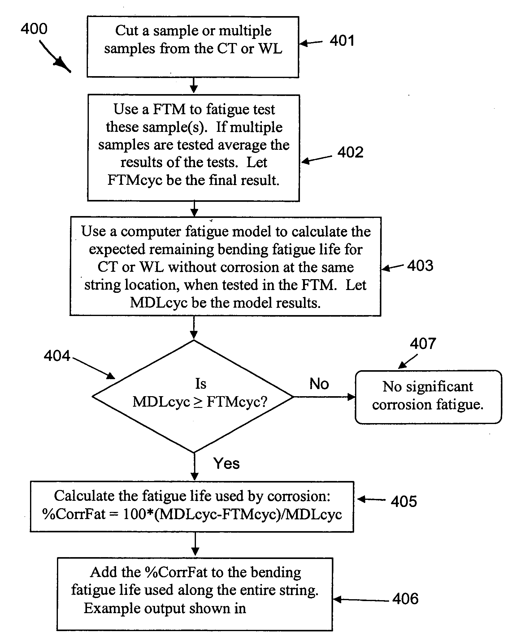
[0044]As illustrated schematically in FIG. 4, in certain embodiments the present invention teaches methods of determining the CT or WL fatigue life reduction due to adverse events, e.g. bending, corrosion, etc. In certain aspects, these methods assume that a downhole end of the CT or WL is as corroded as any other portion of the CT or WL. In other aspects, methods according to the present invention focus on a portion or portions of CT or WL which is broken or in which significant corrosion is suspected.

[0045]When the CT or WL has been used and has suffered due to adverse events, a sample or multiple samples are taken (e.g. cut) from the CT or WL (step 401). The length of these samples is defined by the FTM which will be used in a testing step. In certain aspects, typical samples range between one foot and nine feet in length.

[0046]The sample or samples are tested using a FTM (step 402), producing a measured number of cycles to failure for the specific configuration of the FTM test (...


PUM


Abstract

A method for determining fatigue life reduction in a string; the method, in at least certain aspects, including providing at least one sample from a string that has been subjected to corrosion, fatigue testing the at least one sample to determine a measured remaining fatigue life, calculating an expected remaining bending fatigue life for the at least one sample, and comparing the measured remaining fatigue life to the expected remaining bending fatigue life to determine the extent of reduction in fatigue life of the string.

Description

BACKGROUND OF THE INVENTION[0001]1. Field of the Invention[0002]The present invention is directed to fatigue measurement of pipe, wire, and wireline.[0003]2. Description of Related Art[0004]Coiled tubing (“CT”) is pipe which can be run in and out of a pipeline, tubular string, borehole, or wellbore. CT is typically made of steel alloys including carbon steel and stainless steel. The CT is stored on and spooled from a reel. In winding onto the reel, the CT is bent. Typically the CT is fed or spooled from the reel over a gooseneck or guide arch or an injector for directing the CT into a bore or well. When run into and out of a well, the CT is straightened as it comes off of the reel, bent as it goes around the guide arch, and straightened as it goes through the injector and into the well. When being pulled out of a well, the CT is bent around the guide arch, straightened as it goes towards the reel, then bent onto the reel. Thus in one trip in and out of a well, a given section of the...

Claims


Application Information

Patent Timeline
Patent Type & Authority Applications(United States)
IPC IPC(8): G06F19/00
CPCG01N3/32G01N2203/0073G01N2203/0023
Inventor NEWMAN, KENNETH RAY
Owner COILED TUBING ENG SERVICES
Why Eureka
Try Eureka