Fast L1 flush mechanism

a technology of l1 and l1, applied in the field of fast l1 flush mechanism, can solve the problems of affecting the overall processor design, and affecting the accuracy of the overall processor

Active Publication Date: 2008-03-27
APPLE INC
View PDF9 Cites 112 Cited by
  • Summary
  • Abstract
  • Description
  • Claims
  • Application Information

AI Technical Summary

Benefits of technology

[0007]In one embodiment, a processor comprises a data cache configured to store a plurality of cache blocks and a control unit coupled to the data cache. The control unit is configured to flush the plurality of cache blocks from the data cache responsive to an indication that the processor is to transition to a low power state in which one or more clocks for the processor are inhibited.
[0008]In another embodiment, a system comprises a processor comprising a data cache configured to store a plurality of cache blocks and a secondary cache coupled to the processor. The processor is configured to flush the plurality of cache blocks from the data cache responsive to an indication that the processor is to transition to a low power state in which one or more clocks for the processor are inhibited. The flush comprises writing any modified cache blocks of the plurality of cache blocks to the secondary cache.
[0009]In yet another embodiment, a method comprises determining that a processor is to transition to a low power state in which one or more clocks used by the processor are inhibited; and flushing a plurality of cache blocks from a data cache within the processor responsive to determining that the processor is to transition to the low power state.

Problems solved by technology

In other low power states, the supply voltage may be deactivated as well and the processor state is lost.
A challenge in processors that implement low power states in which the supply voltage is maintained, and thus the caches retain their state, is the maintenance of coherency in the caches with respect to any memory transactions that may be generated by other devices / processors while the processor is in the low power state.
The cache and related circuitry is thus in a different clock domain than the rest of the processor, which complicates the overall processor design.

Method used


Image

  • Fast L1 flush mechanism
  • Fast L1 flush mechanism
  • Fast L1 flush mechanism

Examples


Embodiment Construction

System Overview

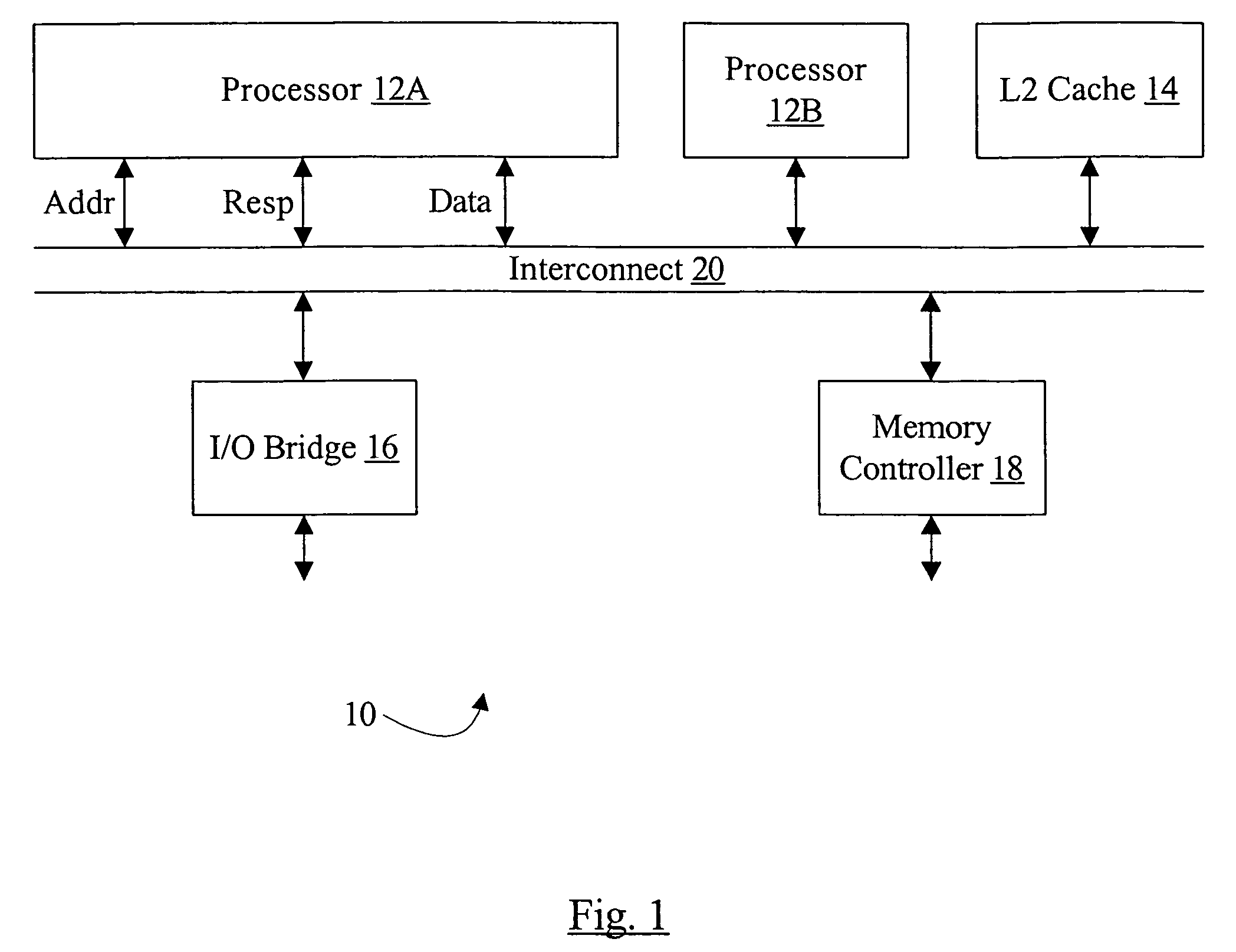
[0017]Turning now to FIG. 1, a block diagram of one embodiment of a system 10 is shown. In the illustrated embodiment, the system 10 includes processors 12A-12B, a level 2 (L2) cache 14, an I / O bridge 16, a memory controller 18, and an interconnect 20. The processors 12A-12B, the L2 cache 14, the I / O bridge 16, and the memory controller 18 are coupled to the interconnect 20. More particularly, as illustrated with regard to the processor 12A, the agent coupled to the interconnect 20 may communicate via transactions having address, response, and data phases on the interconnect 20. While the illustrated embodiment includes two processors 12A-12B, other embodiments of the system 10 may include one processor or more than two processors. Similarly, other embodiments may include more than one L2 cache 14, more than one I / O bridge 16, and / or more than one memory controller 18. In one embodiment, the system 10 may be integrated onto a single integrated circuit chip (e.g. a sys...


PUM


Abstract

In one embodiment, a processor comprises a data cache configured to store a plurality of cache blocks and a control unit coupled to the data cache. The control unit is configured to flush the plurality of cache blocks from the data cache responsive to an indication that the processor is to transition to a low power state in which one or more clocks for the processor are inhibited.

Description

BACKGROUND[0001]1. Field of the Invention[0002]This invention is related to the field of processors and, more particularly, to handling caches and cache coherency in power management modes in processors.[0003]2. Description of the Related Art[0004]As the power consumption of processors has increased, implementation of power management modes in processors has become increasing important. In many systems, the power supply is at least sometimes a battery or other stored-charge supply. Maximizing battery life in such systems is often a key selling feature. Additionally, even in systems that have effectively limitless power (e.g. systems plugged into a wall outlet), the challenges of cooling the processors and other circuits in the system may be reduced if the processors can be placed in low power modes when full processing power is not needed.[0005]A variety of power management schemes are in use. Typically, the processor may be operated in one of a set of power states. The highest powe...

Claims


Application Information

Patent Timeline
Patent Type & Authority Applications(United States)
IPC IPC(8): G06F1/32
CPCG06F1/3203Y02B60/32Y02B60/1221G06F1/3237Y02D10/00Y02D30/50
Inventor KELLER, JAMES B.YEH, TSE-YUGUNNA, RAMESHCAMPELL, BRIAN J.
Owner APPLE INC
Why Eureka
Try Eureka