Method for assembling a modular fluid end for duplex pumps

a technology of modular fluid end and duplex pump, which is applied in the direction of piston pump, positive displacement liquid engine, borehole/well accessories, etc., can solve the problems of fluid end washout, mud pump fluid end failure, and corrosive and/or abrasive fluid that may be pumped

Inactive Publication Date: 2008-04-03
EC TOOL & SUPPLY
View PDF1 Cites 28 Cited by
  • Summary
  • Abstract
  • Description
  • Claims
  • Application Information

AI Technical Summary

Benefits of technology

[0016]The claimed subject matter is not limited to implementations that solve any or all of the noted disadvantages. Further, the summary section is provided to introduce a selection of concepts in a simplified form that are further described below in the detailed description section. The summary section is not intended to identify key features or essential features of the claimed subject matter, nor is it intended to be used to limit the scope of the claimed subject matter.

Problems solved by technology

In addition, the fluid that may be pumped may be corrosive and / or abrasive.
The high pumping pressures and corrosive and abrasive nature of the fluid often cause washouts in the fluid end.
Washouts in the pistons, cylinders, valves and other components of the fluid end may be the most common cause of mud pump fluid end failure.
Both of these methods are expensive and time consuming.

Method used


Image

  • Method for assembling a modular fluid end for duplex pumps
  • Method for assembling a modular fluid end for duplex pumps
  • Method for assembling a modular fluid end for duplex pumps

Examples


Embodiment Construction

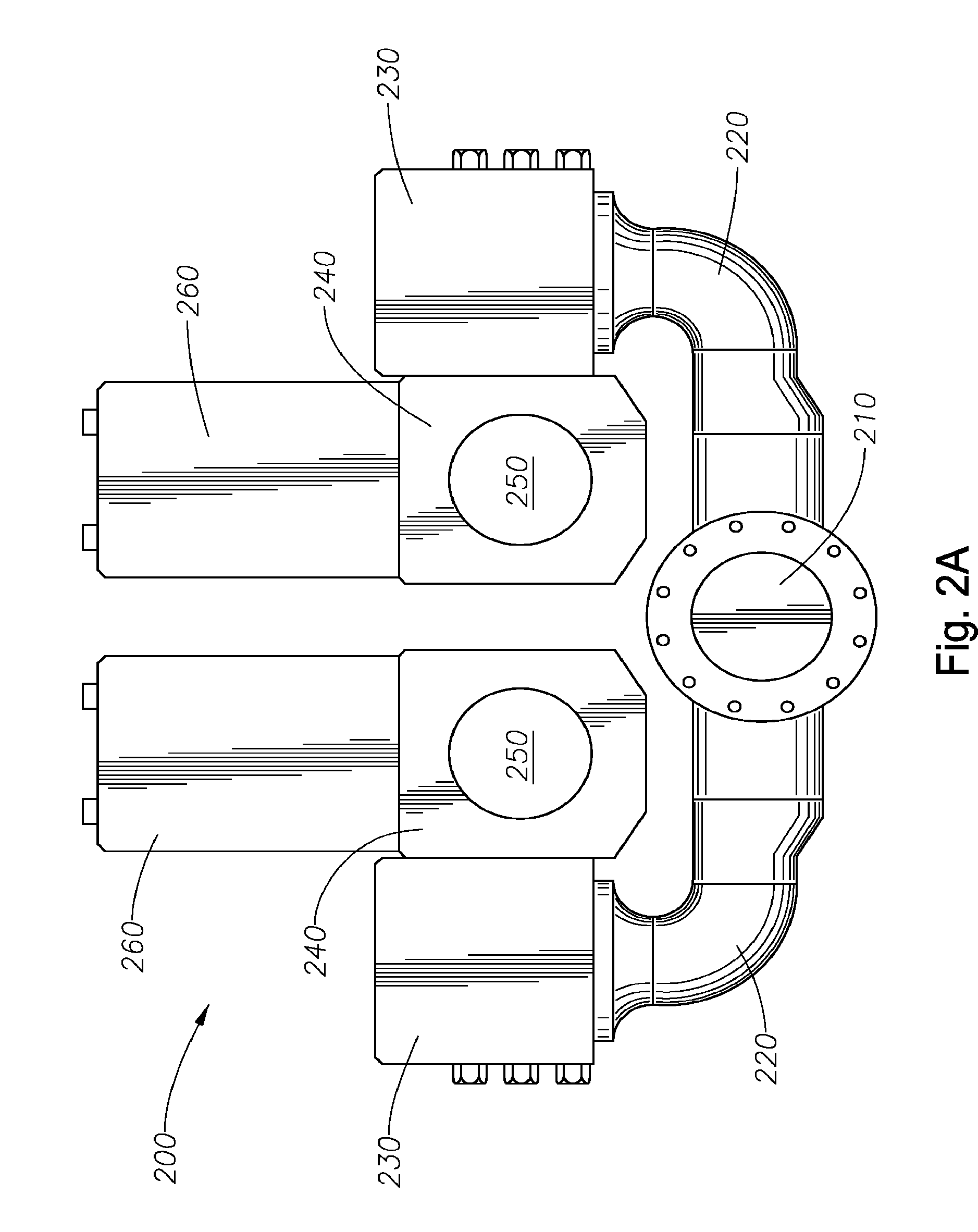
[0026]FIGS. 2A-B illustrate a fluid end 200 of a duplex mud pump in connection with various technologies described herein. FIG. 2A illustrates a side view of a fluid end 200, while FIG. 2B illustrates a top view of the fluid end 200. As previously mentioned above, a fluid end 200 refers to that part of the pump apparatus that moves fluid from a pump inlet to a pump discharge. The fluid end 200 may include a fluid inlet 210 which allows fluid from the fluid / mud tank to enter a suction manifold 220. The suction manifold 220 carries the fluid to four suction valve blocks 230. Two suction valve blocks 230 may be side mounted on each of two liner blocks 240. The suction valve blocks 230 may operate to control the fluid flow into the two liner blocks 240. One reciprocating piston enters each of the two liner blocks 240 at the piston inlets 250. The pistons (not shown) may operate to force the fluid out of the liner blocks 240 into four discharge valve blocks 260. Each liner block 240 has ...


PUM


Abstract

A fluid end for a duplex mud pump. In one implementation, the fluid end includes two liner blocks, each having a central passage. The fluid end further includes two fluid inlets disposed on a side portion and two fluid outlets disposed on a top portion and a suction manifold displaced from the two liner blocks. The suction manifold comprises four flanges. The fluid end further includes four suction valve blocks, each having a bottom portion removably coupled to one of the four flanges and a side portion removably coupled to the side portion of the liner block, and four discharge valve blocks, each having a bottom portion removably coupled to the top portion of the liner block.

Description

CROSS-REFERENCE TO RELATED APPLICATIONS[0001]This application is a divisional of co-pending U.S. patent application Ser. No. 11 / 536,260, filed Sep. 28, 2006. The aforementioned related patent application is herein incorporated by reference.BACKGROUND[0002]1. Field of the Invention[0003]Implementations of various technologies described herein generally relate to mud pumps, particularly duplex mud pumps.[0004]2. Description of the Related Art[0005]The following descriptions and examples are not admitted to be prior art by virtue of their inclusion within this section.[0006]In extracting hydrocarbons, such as oil and gas, from the earth, it is common to drill a wellhole into the formation containing the hydrocarbons. Typically, a drill bit is attached to a drill string, including joined sections of drill pipe, which may be suspended from a drilling rig. As the drill bit rotates, the hole deepens and the string is lengthened by attaching additional sections of drill pipe. During such dr...

Claims


Application Information

Patent Timeline
Patent Type & Authority Applications(United States)
IPC IPC(8): E21B21/01
CPCF04B15/02
Inventor CUMMINS, MILBURN EUGENE
Owner EC TOOL & SUPPLY
Why Eureka
Try Eureka