Impedance-controlled pseudo-open drain output driver circuit and method for driving the same

a pseudo-open drain and output driver technology, applied in logic circuits, pulse techniques, reliability increasing modifications, etc., can solve the problems of error occurring when resistance is matched at the outside, and conventional pseudo-open drain output driver circuits are not suitable for high-speed operation, so as to minimize the occurrence of impedance matching errors and reduce the impedance locking time

Inactive Publication Date: 2008-04-03
SK HYNIX INC
View PDF4 Cites 19 Cited by
  • Summary
  • Abstract
  • Description
  • Claims
  • Application Information

AI Technical Summary

Benefits of technology

[0007] Embodiments of the present invention are directed to an impedance-controlled pseudo-open drain output d

Problems solved by technology

However, the conventional pseudo-open drain output driver circuit is not suitable for high-speed operation because

Method used


Image

  • Impedance-controlled pseudo-open drain output driver circuit and method for driving the same
  • Impedance-controlled pseudo-open drain output driver circuit and method for driving the same
  • Impedance-controlled pseudo-open drain output driver circuit and method for driving the same

Examples


Embodiment Construction

[0017] In the conventional impedance-controlled pseudo-open drain output driver circuit, an impedance matching error occurs due to the use of external resistors, and an impedance locking time increases due to the implementation of the closed-loop circuits. However, the impedance-controlled pseudo-open drain output driver circuit in accordance with the embodiments of the present invention can minimize the impedance matching error by using internal control circuits, instead of external impedance matching resistors. Further, the impedance locking can be achieved through the open-loop configuration within one clock period, thereby realizing the clock-on-demand. Moreover, the output driver circuit is controlled using CMOS digital logics, thereby reducing chip area and power consumption.

[0018] Hereinafter, an impedance-controlled pseudo-open output driver circuit in accordance with the present invention will be described in detail with reference to the accompanying drawings.
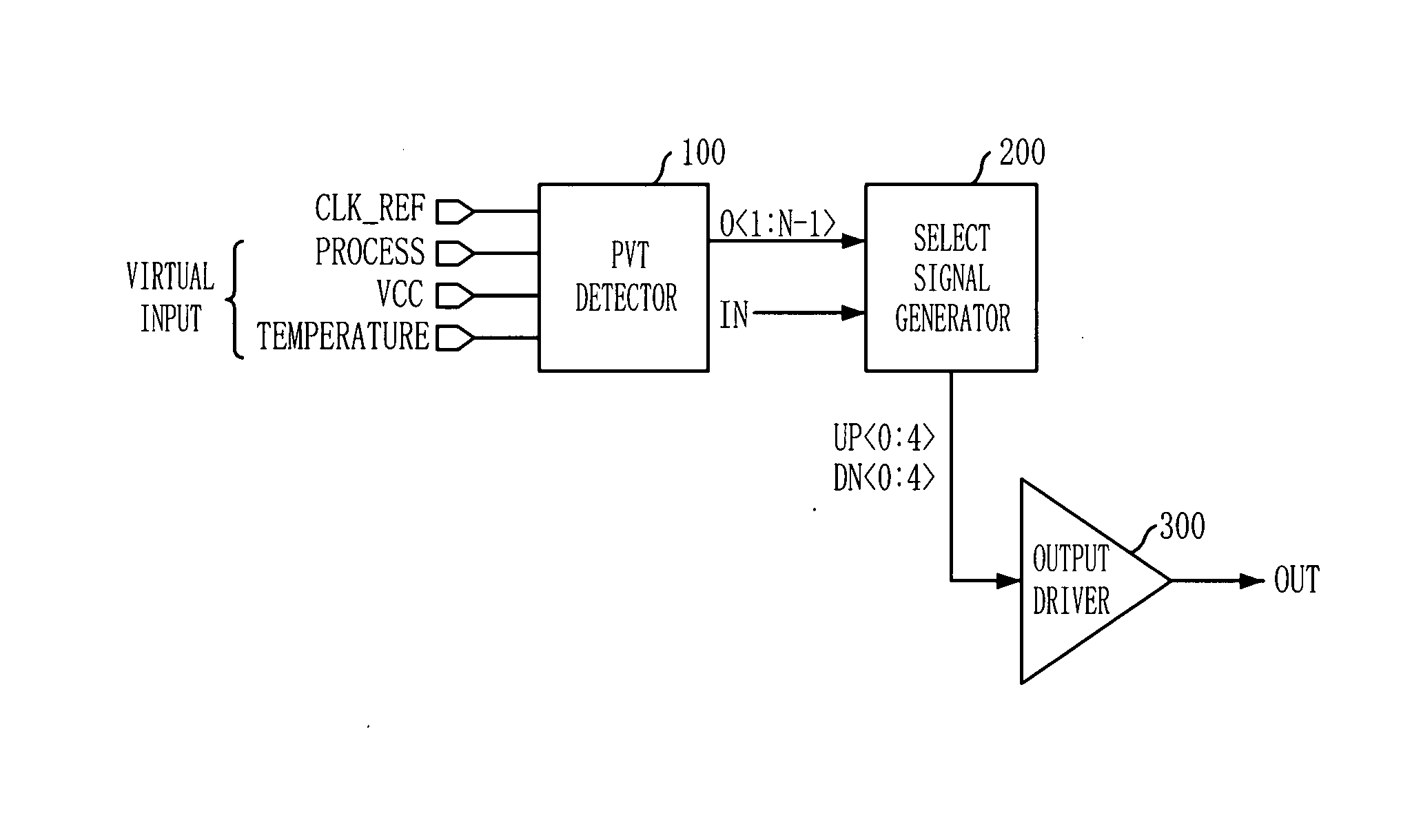
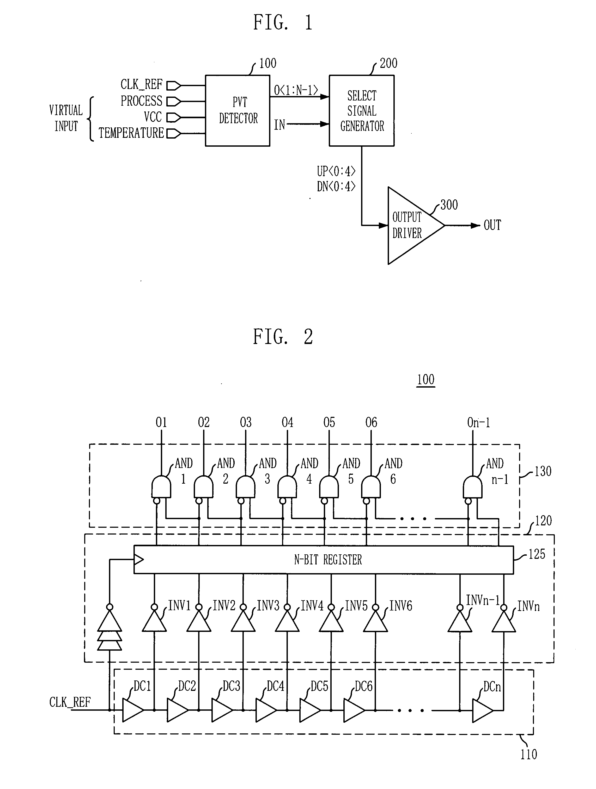
[0019]FIG. 1...


PUM


Abstract

An impedance-controlled pseudo-open drain output driver circuit includes: a process, voltage, and temperature (PVT) detector configured to have a delay line receiving a reference clock and detect a state variation of the delay line according to PVT conditions to output detection signals; a select signal generator configured to generate a driving select signal based on the detection signals and an output data; and an output driver configured to drive an output terminal, the output driver including a plurality of pull-up/pull-down driving blocks controlled by the driving select signal, each of the pull-up/pull-down driving blocks including a resistor having an intended impedance.

Description

CROSS-REFERENCE TO RELATED APPLICATIONS [0001] The present invention claims priority of Korean patent application number 10-2006-0097295, filed on Oct. 2, 2006, which is incorporated by reference in its entirety. BACKGROUND OF THE INVENTION [0002] The present invention relates to a semiconductor device, and more particularly, to an impedance-controlled pseudo-open drain output driver circuit and a method for driving the same. [0003] An output driver circuit is an interface circuit to drive an output pad (DQ), to which a predetermined load is connected, so as to output an internal data of a semiconductor device to an external circuit. [0004] A pseudo-open drain driver is an interface circuit adopted as a standard in Graphics Double Data Rate 3 (GDDR3). While a push-pull driver is based on a current, a pseudo-open drain driver is based on a voltage. [0005] To control an output impedance, a conventional pseudo-open drain output driver circuit repeats a process of changing an impedance ...

Claims


Application Information

Patent Timeline
IPC IPC(8): H03K19/0185
CPCH03K19/00384G11C7/04G11C7/10G11C8/08
Inventor SHIN, DONG-SUKJUNG, INHWAKIM, CHULWOOLEE, HYUNG-DONGCHOI, YOUNG-JUNG
Owner SK HYNIX INC
Why Eureka
Try Eureka