Thermoanalytical sensor

a technology of analytic sensors and sensors, applied in the field of thermoanalytical sensors, can solve the problems of low mechanical and/or chemical endurance, high production process costs, and in many cases low sensitivity, and achieve the effect of greater structural flexibility and higher sensitivity

Active Publication Date: 2008-04-03
METTLER TOLEDO GMBH
View PDF42 Cites 16 Cited by
  • Summary
  • Abstract
  • Description
  • Claims
  • Application Information

AI Technical Summary

Benefits of technology

[0013] A thermoanalytical sensor is disclosed for calorimetric measurements which, in comparison to conventional sensors, offers a higher level of sensitivity and, most of all, a greater structural flexibility.

Problems solved by technology

Sensors produced by means of thin-film technology have the disadvantages that the production process is expensive, that the maximum thickness which can be realized is very small, and that they have in many cases a low mechanical and / or chemical endurance.
As a result, the production process in particular for several coating layers is very time-consuming.
The many sintering steps can have a detrimental effect on the structure and the properties of the coating materials involved and / or on the carrier substrate.
Thus, only a part of the heat flow can be measured with a substantially two-dimensional thermocouple arrangement produced with thin- or thick-film technology, so that the result of the measurement carries a corresponding uncertainty.
If the layers consist substantially of structured ceramic elements, it might also be possible that they will not shrink uniformly.

Method used


Image

  • Thermoanalytical sensor
  • Thermoanalytical sensor
  • Thermoanalytical sensor

Examples


Embodiment Construction

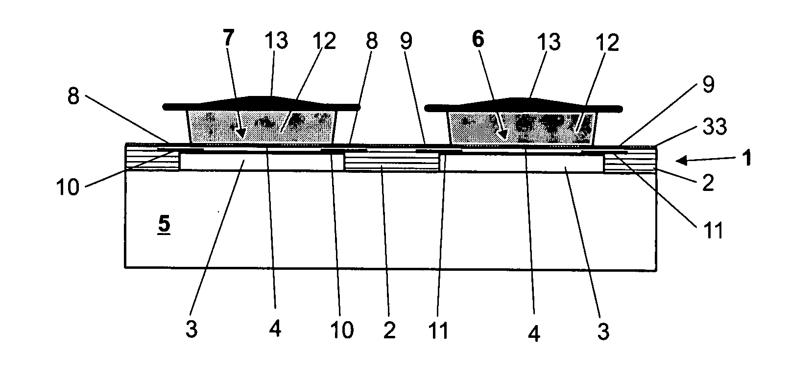
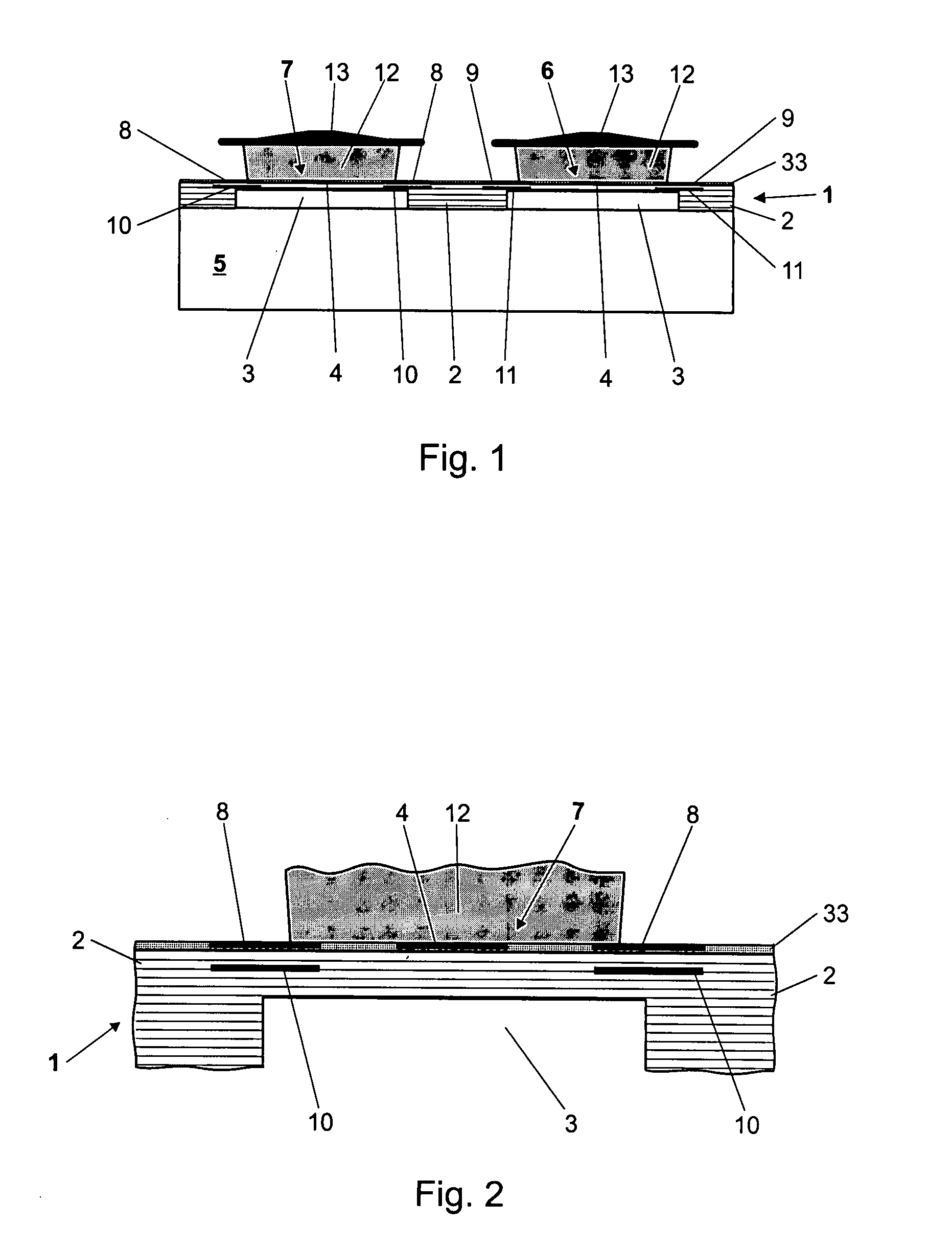
[0068]FIGS. 1 and 2 illustrate an examplary embodiment of a thermoanalytical sensor for calorimetric measuring devices. Shown in FIG. 1 are the substantially disk-shaped sensor 1 which is comprised of a plurality of layers 2 that have been solidly bonded to each other by going through a sintering process together, and at least one coating layer 33 that has been applied to the sensor 1 after the sintering, together with a temperature control device 5 and one cup 12 each for a sample and a reference. For better clarity, FIG. 2 shows an enlarged detail portion of FIG. 1. FIGS. 1 and 2 will be explained together in more detail in the following.

[0069] For a better understanding of the structure of the sensor, the individual layers are shown in all of the drawing figures, although the layers can no longer be fully differentiated from each other after the sintering, but form a nearly monolithic unit in which the individual functional elements are formed.

[0070] The sensor 1 consists of se...


PUM

PropertyMeasurementUnit
thicknessaaaaaaaaaa
thicknessaaaaaaaaaa
thicknessaaaaaaaaaa

Abstract

Thermoanalytical sensor for calorimetric measurements which cooperates with a temperature control device and comprises at least one measurement position formed on the sensor, a heat flow path established between the temperature control device and the at least one measurement position, and at least one temperature-measuring element, characterized in that the sensor has a plurality of layers which are formed substantially by ceramic elements that have been solidly bonded to each other by undergoing a sintering process together and which in their green state can be provided with a structure, wherein at least a part of the ceramic elements are structured.

Description

RELATED APPLICATIONS [0001] This application claims priority under 35 U.S.C. §119 to EP Application 05103341.3 filed in European Patent Office on 25 Apr. 2005, and as a continuation application under 35 U.S.C. §120 to PCT / EP2006 / 061746 filed as an International Application on 21 Apr. 2006 designating the U.S., the entire contents of which are hereby incorporated by reference in their entireties.TECHNICAL FIELD [0002] A thermoanalytical sensor for calorimetric measurements is disclosed. BACKGROUND INFORMATION [0003] Calorimetric measurements serve to determine the amounts of heat turned over in chemical or physical processes as well as the specific heat of a substance. To perform this measurement, the substance or, more specifically, a substance sample, is heated in a calorimeter under controlled conditions, and the heat flow between a substance sample and a temperature control device (i.e. a device for heating and / or cooling) is observed by means of a thermoanalytical sensor. The he...

Claims


Application Information

Patent Timeline
Patent Type & Authority Applications(United States)
IPC IPC(8): G01K7/02G01K17/00
CPCG01K7/028G01N25/4866G01K17/006
Inventor HUETTER, THOMASZUMBACH, MELCHIOR
Owner METTLER TOLEDO GMBH
Why Eureka
Try Eureka