OTDM-DPSK signal generator capable of detecting an optical carrier phase difference between optical pulses

a phase difference and signal generator technology, applied in the field of optical pulse signal generator system, can solve the problems of two sub-signals interfering, difficult for conventional technologies to reduce the fluctuations in the optical path length below a level, and cannot be directly used to provide a system that generates practical otdm-dpsk signals, etc., to achieve the effect of small production, low cost and small production

Active Publication Date: 2008-04-03
OKI ELECTRIC IND CO LTD
View PDF4 Cites 15 Cited by
  • Summary
  • Abstract
  • Description
  • Claims
  • Application Information

AI Technical Summary

Benefits of technology

[0100]The optical carrier interferometer may also preferably include the first half mirror, the ¼-wavelenth plate, the second half mirror, the first ½-bit delay device, the first phase fine adjustment device, the first total reflection mirror, the second total reflection mirror, the third half mirror, the second ½-bit delay device, the second phase fine adjustment device, the third total reflection mirror, and the fourth total reflection mirror. The optical carrier interferometer may thus be manufactured, for small production, as a low cost optical carrier interferometer.
[0101]The optical carrier interferometer may also preferably include the polarizer, the half mirror, the ½-bit delay device, the first total reflection mirror, the first uniaxial crystal, the second total reflection mirror, the second uniaxial crystal, and the analyzer. The optical carrier interferometer may thus be manufactured, for small production, as a low cost and compact optical carrier interferometer.

Problems solved by technology

The OTDM communications system in DPSK scheme disclosed in R. Ludwig, et al., may thus not be directly used to provide a system that generates practical OTDM-DPSK signals.
It is extremely difficult for the conventional technologies to reduce the fluctuations in the optical path length below a level that is negligible compared to zero or π in terms of the optical carrier phase.
The system then provides one sub-signal with one bit delay, and then causes the two sub-signals to interfere again.

Method used


Image

  • OTDM-DPSK signal generator capable of detecting an optical carrier phase difference between optical pulses
  • OTDM-DPSK signal generator capable of detecting an optical carrier phase difference between optical pulses
  • OTDM-DPSK signal generator capable of detecting an optical carrier phase difference between optical pulses

Examples


Embodiment Construction

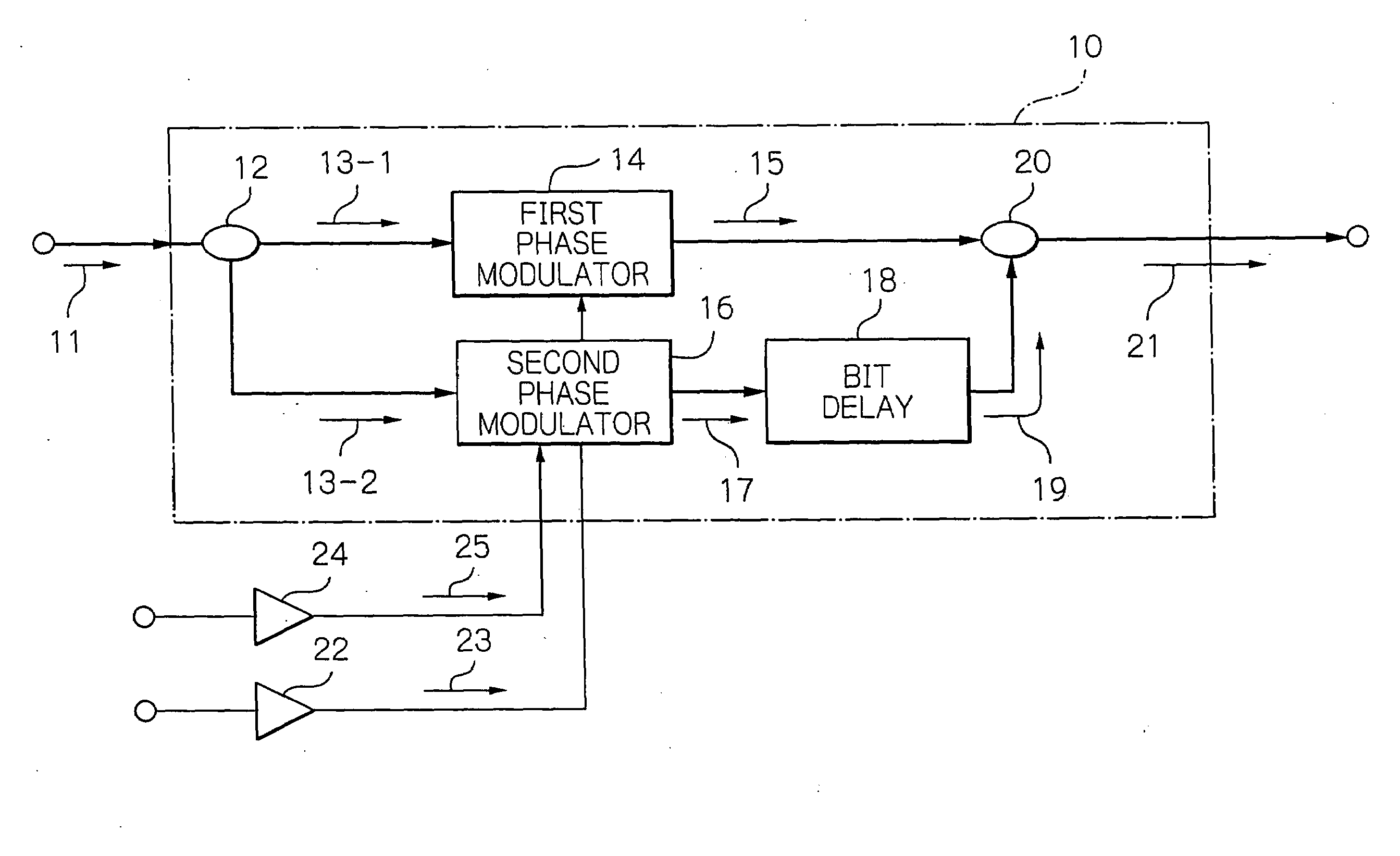
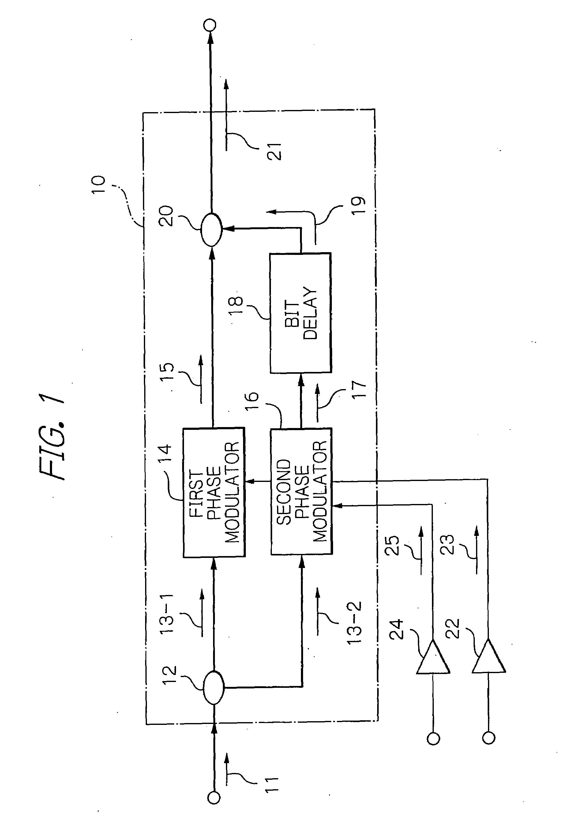
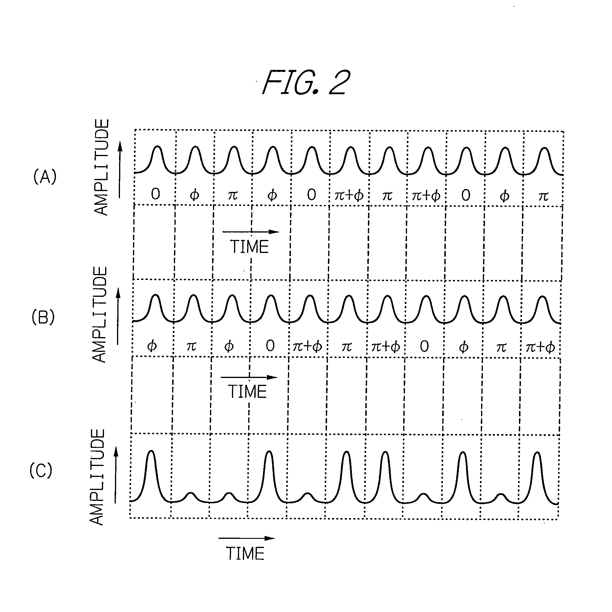
[0122]With reference to the accompanying drawings, preferred embodiments of the present invention will be described in more detail below. Those drawings show exemplified configurations of embodiments of the invention, and are merely intended to schematically show the arrangement or the like of constituent elements to the extent that the present invention can be well understood, and should not be understood to restrict the invention thereby. In the following discussion, specific conditions or the like may be used, but they are merely appropriate examples, and the present invention is not limited thereto.

[0123]In the drawings, arrows are depicted along transmission lines of signals with reference numerals attached thereto to identify the signals propagating over the corresponding transmission lines. Arrows along transmission lines may sometimes be omitted but instead directly provide transmission line with reference numerals that identify signals propagating thereover. Throughout the ...


PUM


Abstract

An OTDM-DPSK signal generator includes an optical splitter, a first and a second phase modulator, an optical coupler, and a monitor signal splitter. The optical splitter splits an optical pulse string into a first and a second optical pulse string. The first and second phase modulators generate a first and a second channel DPSK signal, respectively. The DPSK signals are provided with one bit delay to generate another DPSK signal, which enters the optical coupler, which outputs an OTDM-DPSK signal, which enters a monitor signal splitter. The monitor signal splitter splits from the OTDM-DPSK signal a monitor signal and inputs the monitor signal to an optical carrier phase difference detector. The detector generates an optical carrier phase difference detection signal as a function of an optical carrier phase difference between optical pulses. The optical carrier phase difference can thus be detected between optical pulses in an OTDM-DPSK signal.

Description

BACKGROUND OF THE INVENTION[0001]1. Field of the Invention[0002]The present invention relates to an optical pulse signal generator system that provides an optical pulse signal coded in the differential phase shift keying (DPSK) scheme with an optical time division multiplexing (OTDM), thus generating and outputting an optical time division multiplexing differential phase shift keying (OTDM-DPSK) signal, and more particularly to a system for detecting an optical carrier phase difference between optical pulses in an OTDM-DPSK signal and to a system for controlling an optical carrier phase difference between optical pulses.[0003]2. Description of the Background Art[0004]In the field of optical communications technology, the intensity modulation-direct detection (IM-DD) scheme and the balanced detection scheme are proposed, see, for example, R. Ludwig, et al., “160 Gbit / s DPSK-Transmission-Technologies and System Impact” Proc. 30th European Conference on Optical Communication (ECOC 2004...

Claims


Application Information

Patent Timeline
Patent Type & Authority Applications(United States)
IPC IPC(8): H04J14/08H04B10/516H04B10/556H04B10/61H04J14/00H04J14/04H04J14/06
CPCH04B10/505H04B10/5053H04J14/086H04B10/5561H04B10/50575
Inventor KAGAWA, MASATOSHI
Owner OKI ELECTRIC IND CO LTD
Why Eureka
Try Eureka