Motor spindle as a rotary drive for tools on a machine tool

a technology of rotary drive and motor spindle, which is applied in the direction of driving apparatus, large fixed members, milling equipment, etc., can solve the problem of being subject to the most load

Inactive Publication Date: 2008-04-03
MASCHFAB BERTHOLD HERMLE
View PDF7 Cites 18 Cited by
  • Summary
  • Abstract
  • Description
  • Claims
  • Application Information

AI Technical Summary

Benefits of technology

[0004]One object of the invention is to so redesign a motor spindle of the type initially mentioned that simple dismantling of the initially mentioned tool holder means together with the spindle shaft may be so implemented that the bearing of the motor shaft remains unimpaired and the spindle motor does not have to be detached at all.
[0006]The advantages of the motor spindle in accordance with the invention are more especially that owing to the modular construction, that is to say the separate bearing means for the motor shaft in the motor housing and the spindle shaft, in the spindle housing and also the axially freely sliding of the spindle shaft coupled with the motor shaft a rapid and simpler detachment of the spindle housing from the motor housing may take place, it merely being necessary to undo housing screws. The spindle motor itself is then not impaired in any way. Furthermore owing to the axial sliding coupling between the motor shaft and the spindle shaft it is possible for the drive motor with its bearings to be relatively simply protected against axial impacts due to collisions. If it comes a collision the spindle shaft may be axially shifted without forces being transmitted to the bearings of the motor. A further substantial advantage is that on separating the spindle housing from the motor housing the tool holder means or, respectively, their draw rod may be pulled out as well without any dismantling operations being necessary for this purpose. The most wear-prone parts of a motor spindle are normally the tool holder means, whose disk spring stack must normally be replaced after a certain number of clamping strokes, and the bearing of the spindle shaft, which during a machining using one tool are subject to most load. Owing to the simple and rapid detachment of the spindle housing such detachment may take place on site and on the other hand all particularly wear-prone parts may be detached as a single assembly. On site a new assembly may be employed without any major adjustment operations or dynamic balancing operations being necessary.
[0008]The coupling, which is interlocking in the direction of rotation, between the spindle shaft and the motor shaft and which permits a mutual axial displacement, is preferably designed in the form of gear splines and more particularly in the form of a ring of splines. Preferably in this respect the motor shaft has a spline ring portion with internal splines with which aa splined hub of the spindle shaft interlocks. This renders possible a particularly simple and rapid uncoupling and coupling by sliding inward or outward.

Problems solved by technology

The most wear-prone parts of a motor spindle are normally the tool holder means, whose disk spring stack must normally be replaced after a certain number of clamping strokes, and the bearing of the spindle shaft, which during a machining using one tool are subject to most load.

Method used


Image

  • Motor spindle as a rotary drive for tools on a machine tool
  • Motor spindle as a rotary drive for tools on a machine tool
  • Motor spindle as a rotary drive for tools on a machine tool

Examples


Embodiment Construction

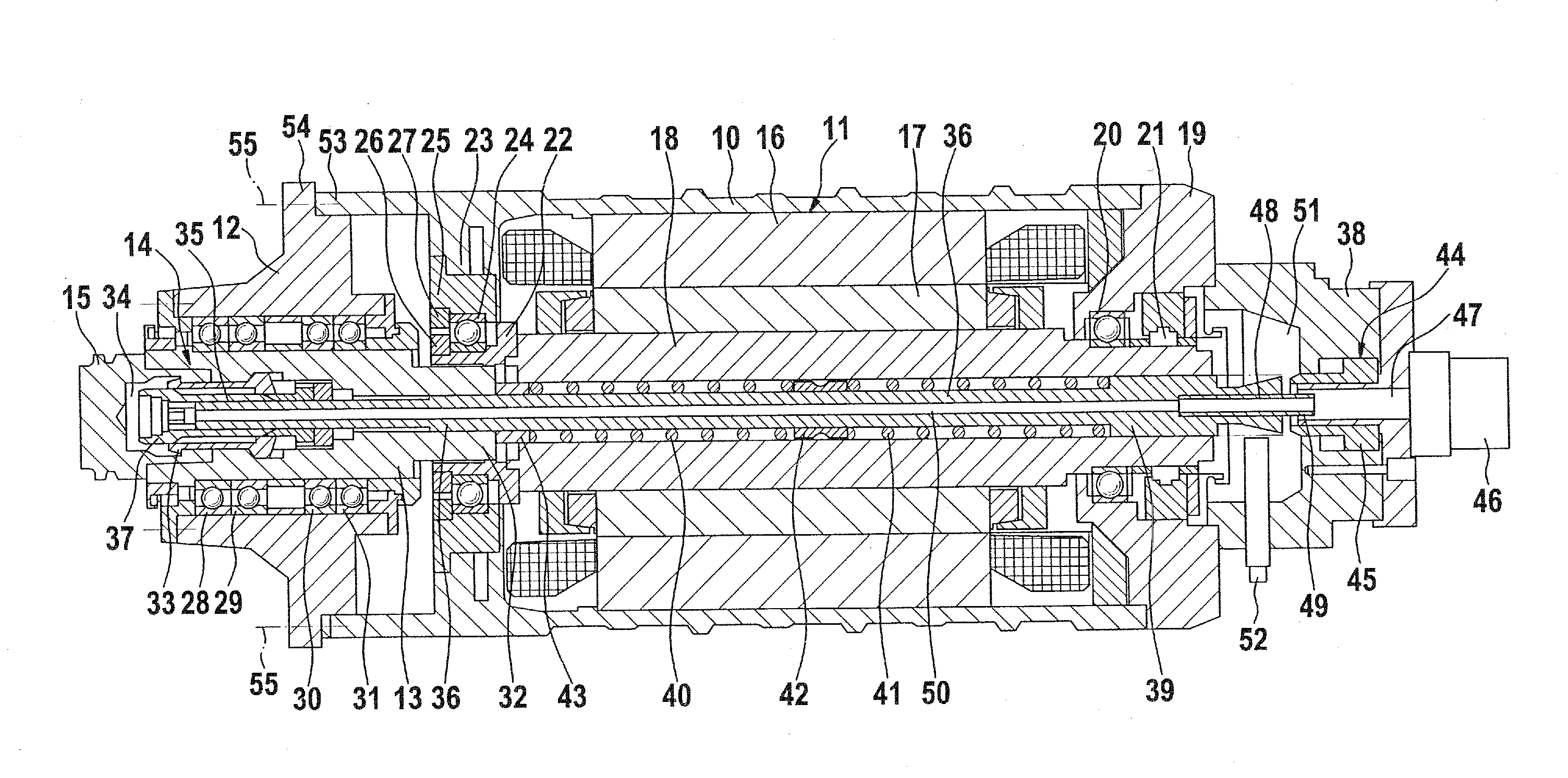
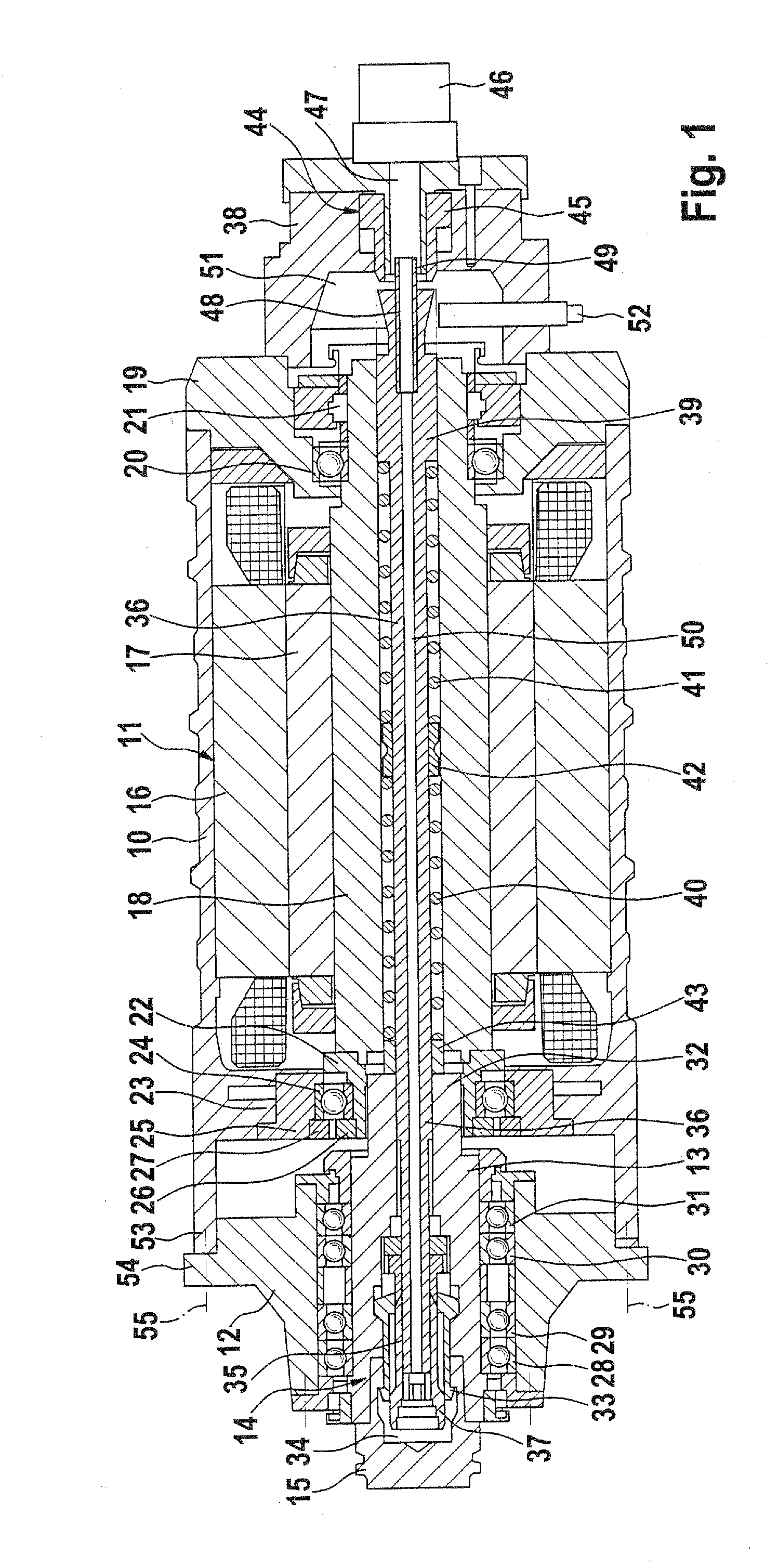
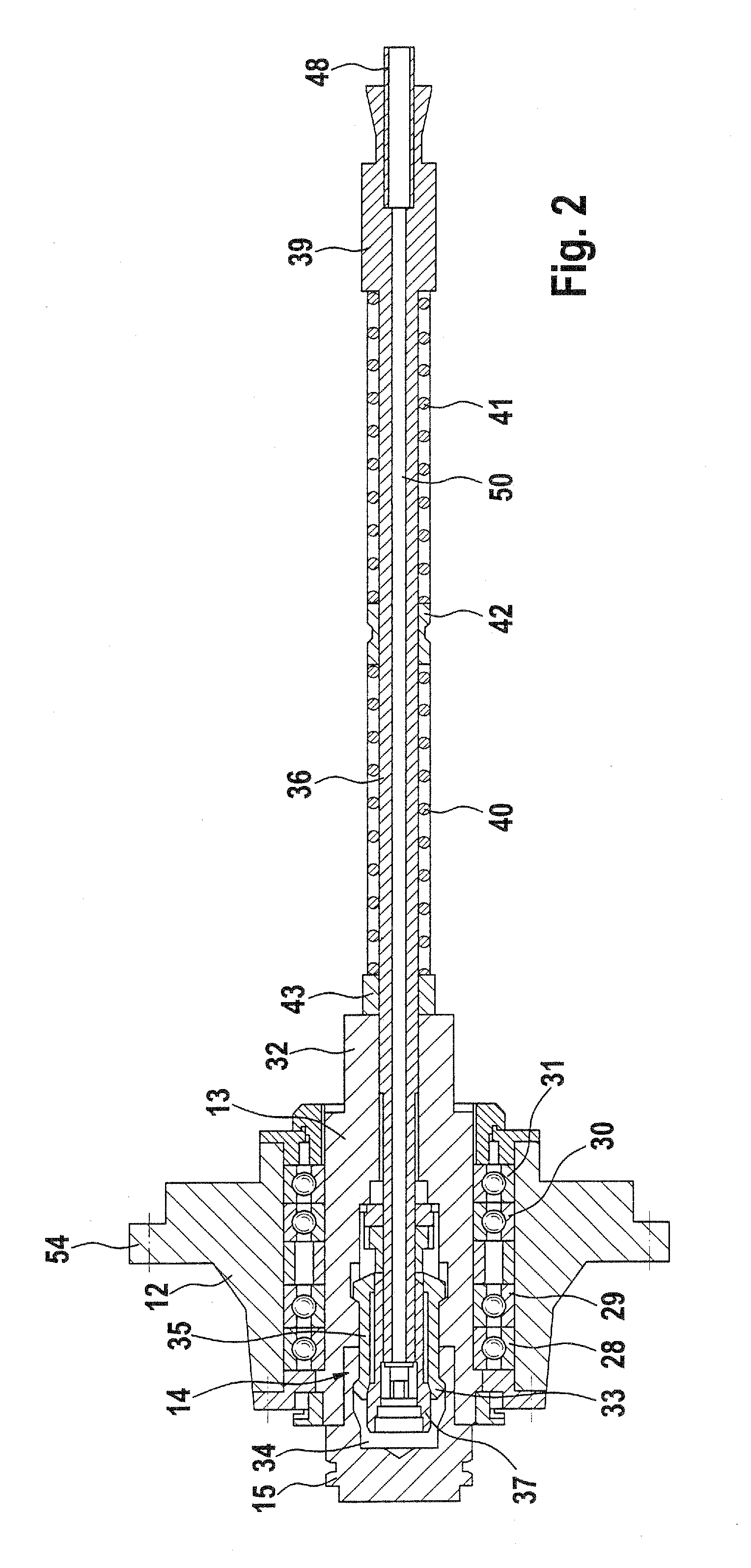
[0019]The motor spindle depicted in the figures is designed in a compact fashion and serves to drive cutting tools in rotation on a machine tool. The motor spindle includes two housings which are screwed together, namely a motor housing 10 for a spindle motor 11 and a spindle housing 12, for a spindle shaft 13 and a tool holder means 14 for clamping a machining cool or a tool receiving means 15 holding such a cutting cool.

[0020]The spindle motor 11 in the motor housing 10 exhibits an external stator 16 and an internal rotor 17, which

[0021]fits around a motor shaft 18 in the form of a hollow shaft. The motor housing 11 is terminated at an end portion, remote from the spindle housing 12, by a pillow block 19, which contains an anti-friction bearing 20 as a rotary bearing for the motor shaft 18 on this one side. Moreover, in this pillow block 19 there is a rotation sensor 21 responsive to the speed of rotation of the motor shaft 18 and thus of the spindle motor 11.

[0022]The motor shaft...


PUM

PropertyMeasurementUnit
speedaaaaaaaaaa
axial displacementaaaaaaaaaa
clamping forceaaaaaaaaaa

Abstract

A motor spindle for causing rotation of tools on a machine tool has a spindle motor with a motor shaft and a spindle shaft driven by the motor shaft and having a tool clamping means. From the tool clamping means there extends through the spindle shaft and the motor shaft an axially sliding draw rod for clamping tools or tool receiving means. The motor shaft is supported in a rotatable fashion, independently of the spindle shaft in a motor housing and the spindle shaft is supported independently from the motor shaft in a spindle housing, which is attached to the motor housing in a detachable manner. The spindle shaft is coupled in an interlocking manner in the direction of rotation with the motor shaft but is able to freely slide in it. The spindle housing constitutes a single structural unit with the tool clamping means and its draw rod, such draw rod being accommodated in the motor shaft for free sliding motion with the result that the entire structural unit can be removed without the spindle motor or its bearing means being impaired in any way or having to be detached.

Description

BACKGROUND OF THE INVENTION[0001]The invention relates to a motor spindle as a rotary drive for tools on a machine tool, comprising a spindle motor, said spindle motor having a motor shaft, and a spindle shaft driven by said motor shaft and possessing a tool holder means, and a draw rod which extends from the tool holder means through the spindle shaft and the motor shaft in a sliding manner, of the tool holder means for tools or tool receiving means.THE PRIOR ART[0002]In the case of such a modular motor spindle disclosed in the German patent publication DE 2020050180002 U1 with inner coolant supply the motor shaft is identical with the spindle shaft, i. e. the motor shaft also bears the tool holder means for receiving the respective tool. This motor spindle may admittedly be disassembled on site but however it is then necessary to dismantle the drive motor with the entire motor bearings. This procedure with such a complete disassembly of the motor on site has however turned out to ...

Claims


Application Information

Patent Timeline
Patent Type & Authority Applications(United States)
IPC IPC(8): B23C1/00
CPCB23B31/261Y10T409/309464B23Q1/70B23B2250/12B23Q5/10
Inventor BERNHARD, FRANZ-XAVERSCHWCRER, TOBIAS
Owner MASCHFAB BERTHOLD HERMLE
Why Eureka
Try Eureka