Variable valve timing controller for internal combustion engine

a timing controller and variable valve technology, applied in the direction of valve drives, machines/engines, couplings, etc., can solve the problem of slow response speed of the variable valve timing control, and achieve the effect of preventing motor failure and deteriorating durability

Active Publication Date: 2008-04-03
DENSO CORP +1
View PDF6 Cites 15 Cited by
  • Summary
  • Abstract
  • Description
  • Claims
  • Application Information

AI Technical Summary

Benefits of technology

[0007] Hence, the heat value of motor may not exceed the heat generation limit, and it can be prevented that the coil temperature of motor exceeds the allowable temperature range. The durability deterioration and failure of motor can be prevented. In this case, when the motor current is restricted, the speed of response of the variable valve timing control becomes slow.

Problems solved by technology

In this case, when the motor current is restricted, the speed of response of the variable valve timing control becomes slow.

Method used


Image

  • Variable valve timing controller for internal combustion engine
  • Variable valve timing controller for internal combustion engine
  • Variable valve timing controller for internal combustion engine

Examples


first embodiment

[0021] Referring to FIGS. 1 to 9, a first embodiment 1 of the present invention is described hereinafter.

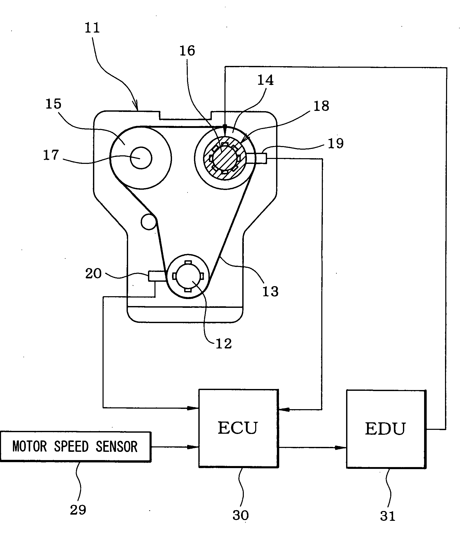
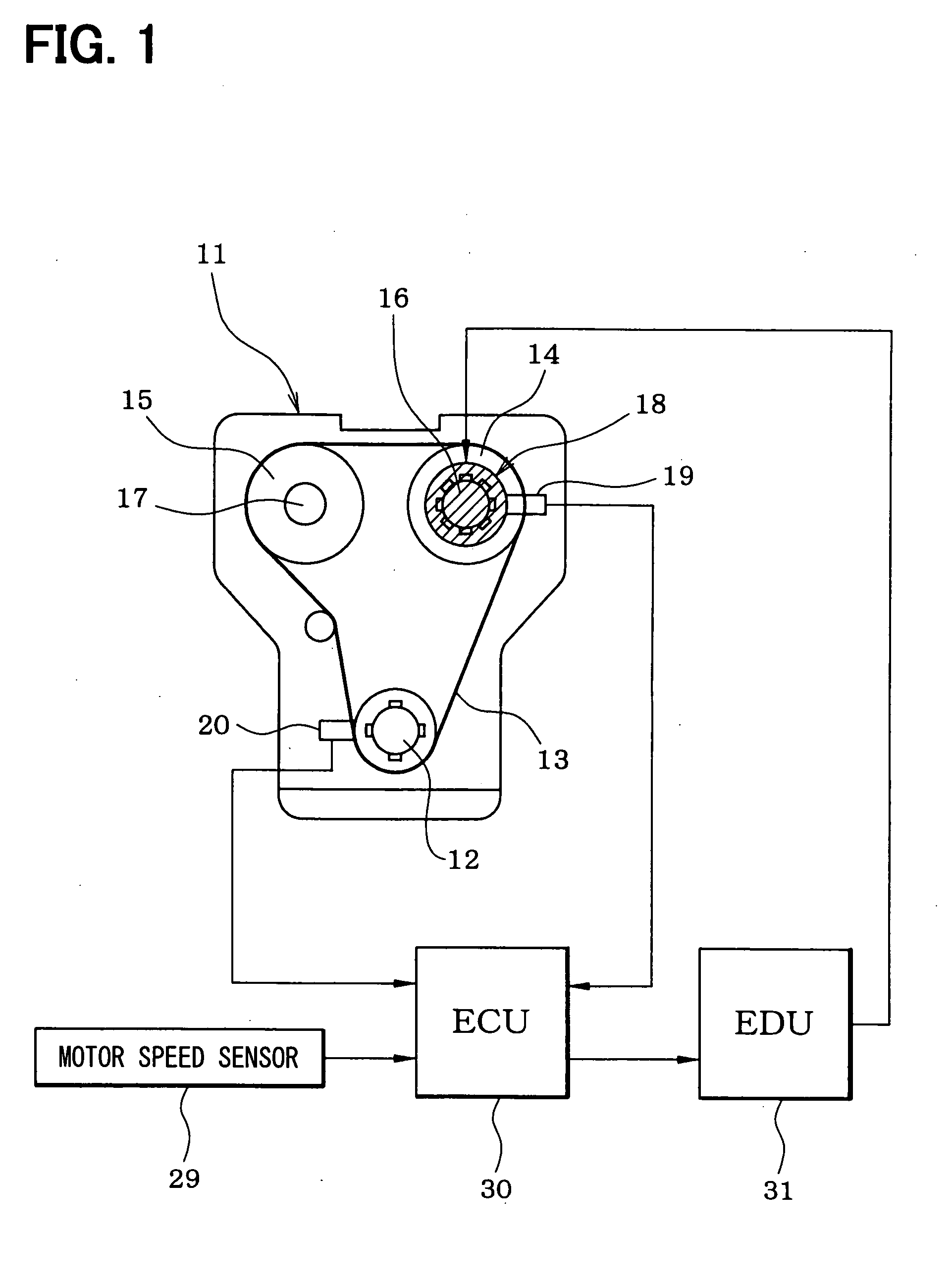
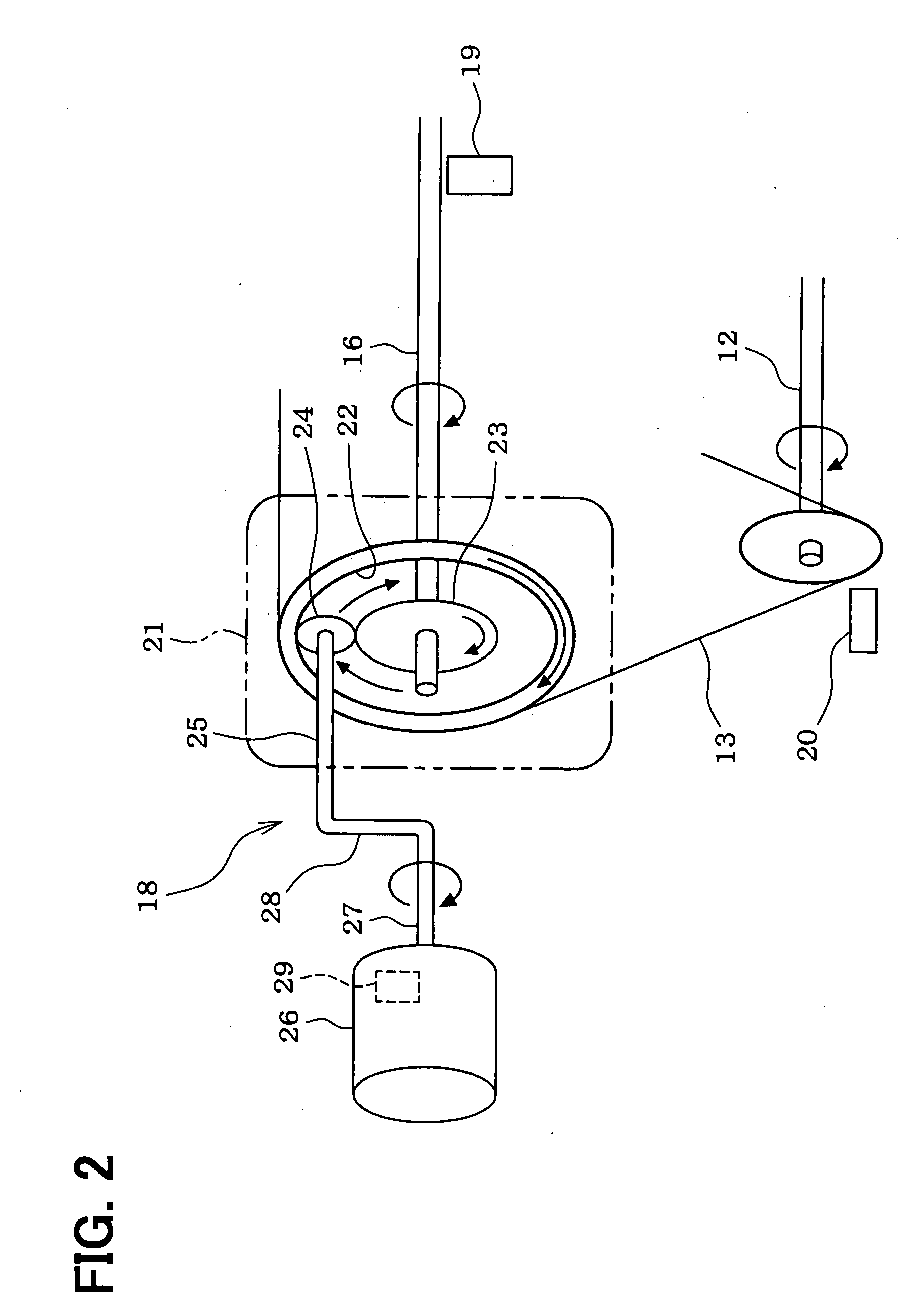
[0022]FIG. 1 schematically shows a whole structure of an engine control system. An internal combustion engine 11, which is referred to as an engine hereinafter, includes a crankshaft 12. A driving force of the crankshaft 12 is transmitted to an intake camshaft 16 and an exhaust camshaft 17 through a timing chain 13 (or a timing belt) and sprockets 14, 15. A variable valve timing controller 18, which includes an electric motor, is coupled to the intake cam shaft 16. The variable valve timing controller 18 varies a rotational phase (camshaft phase) of the intake camshaft 16 relative to the crankshaft 12 so that the valve timing of an intake vale (not shown) is adjusted.

[0023] A cam angle sensor 19 is provided around the intake camshaft 16. The cam angle sensor 19 outputs a cam angle signal every predetermined cam angle of the intake camshaft 16. A crank angle sensor 20 is provide...

second embodiment

[0054] In a second embodiment shown in FIGS. 10 and 11, the duty of the voltage applied to motor 26 is estimated as the information of the motor current, and when the estimated duty exceeds the predetermined value, the variation (motor speed F / B correction amount) in the target motor speed which is outputted to the EDU31 from the ECU30 is restricted, whereby the motor current is restricted. Hereafter, the processing of each program shown in FIGS. 10 and 11 is explained.

[0055] In the target motor speed computation program shown in FIG. 10, processings except steps 103a and 104a are the same as those shown in FIG. 4

[0056] After computing the camshaft phase deviation and the rotational speed F / B correction amount in steps 101 and 102, the procedure proceeds to step 103a in which a duty estimation program shown in FIG. 11 is executed. In step 103a, a duty ratio is estimated based on the instant target motor speed and the instant actual motor speed. Then, the procedure proceeds to step ...

third embodiment

[0062] In first and second embodiments, when the estimated motor current (duty) exceeded the specified value, the motor current is restricted. In a third embodiment shown in FIG. 12, when the estimated motor current (duty) exceeds the specified value, the motor current is intercepted in step 105a and the diagnosis of the variable valve timing controller 18 is stopped in step 106a. The other processings are the same as the first embodiment.

[0063] According to the third embodiment, when the estimated current (duty) exceeds the specified value, the motor current is intercepted to decrease coil temperature of the motor 26. Furthermore, since the diagnosis of variable valve timing controller 18 is stopped, it can prevent an erroneous decision that the state where the variable valve timing control is compulsorily stopped by interception of the motor current is determined as malfunction.

[0064] Besides, the present invention is not limited to the variable valve timing controller of the in...


PUM


Abstract

A motor current (driving current of motor) is estimated based on a target motor speed, an actual motor speed, and an engine speed. When the estimated motor current exceeds the upper limit value equivalent to a heat generation limiting current, the motor current is restricted by restricting a variation (motor speed F/B amount) in target motor speed outputted to an EDU from an ECU. Thereby, the heat value of motor may not exceed the heat generation limit, and it can be prevented that the coil temperature of motor exceeds an allowable temperature range. A durability deterioration and failure of motor can be prevented.

Description

CROSS-REFERENCE TO RELATED APPLICATION [0001] This application is based on Japanese Patent Application No. 2006-233281 filed on Aug. 30, 2006, the disclosure of which is incorporated herein by reference. FIELD OF THE INVENTION [0002] The present invention relates to a variable valve timing controller which includes an electric motor as a driving source. A rotation speed of the electric motor is varied to adjust a rotational phase of the camshaft relative to a crankshaft, whereby a valve timing of an intake valve and / or an exhaust valve of an internal combustion engine is adjusted. BACKGROUND OF THE INVENTION [0003] In order to perform electronic control of the variable valve timing control, the variable valve timing controller which has the motor as a source of the drive has been developed. The variable valve timing controller described in JP-2006-70754A (US2006 / 0042578A1) includes a first gear, a second gear, a phase changing gear, and an electric motor. The first gear (outer gear)...

Claims


Application Information

Patent Timeline
Patent Type & Authority Applications(United States)
IPC IPC(8): F16D3/10
CPCF01L1/352F01L1/34
Inventor TANAKA, TOSHIKAZUINOUE, MASAOMITAKEMURA, YUUICHIMASHIKI, ZENICHIRO
Owner DENSO CORP
Why Eureka
Try Eureka