[0026]Reference will now be made in detail to the present preferred embodiments of the invention, examples of which are illustrated in the accompanying drawings. Wherever possible, the same reference numbers are used in the drawings and the description to refer to the same or like parts.
[0027]While the specification concludes with claims defining the features of the invention that are regarded as novel, it is believed that the invention will be better understood from a consideration of the following description in conjunction with the figures, in which like reference numerals are carried forward.
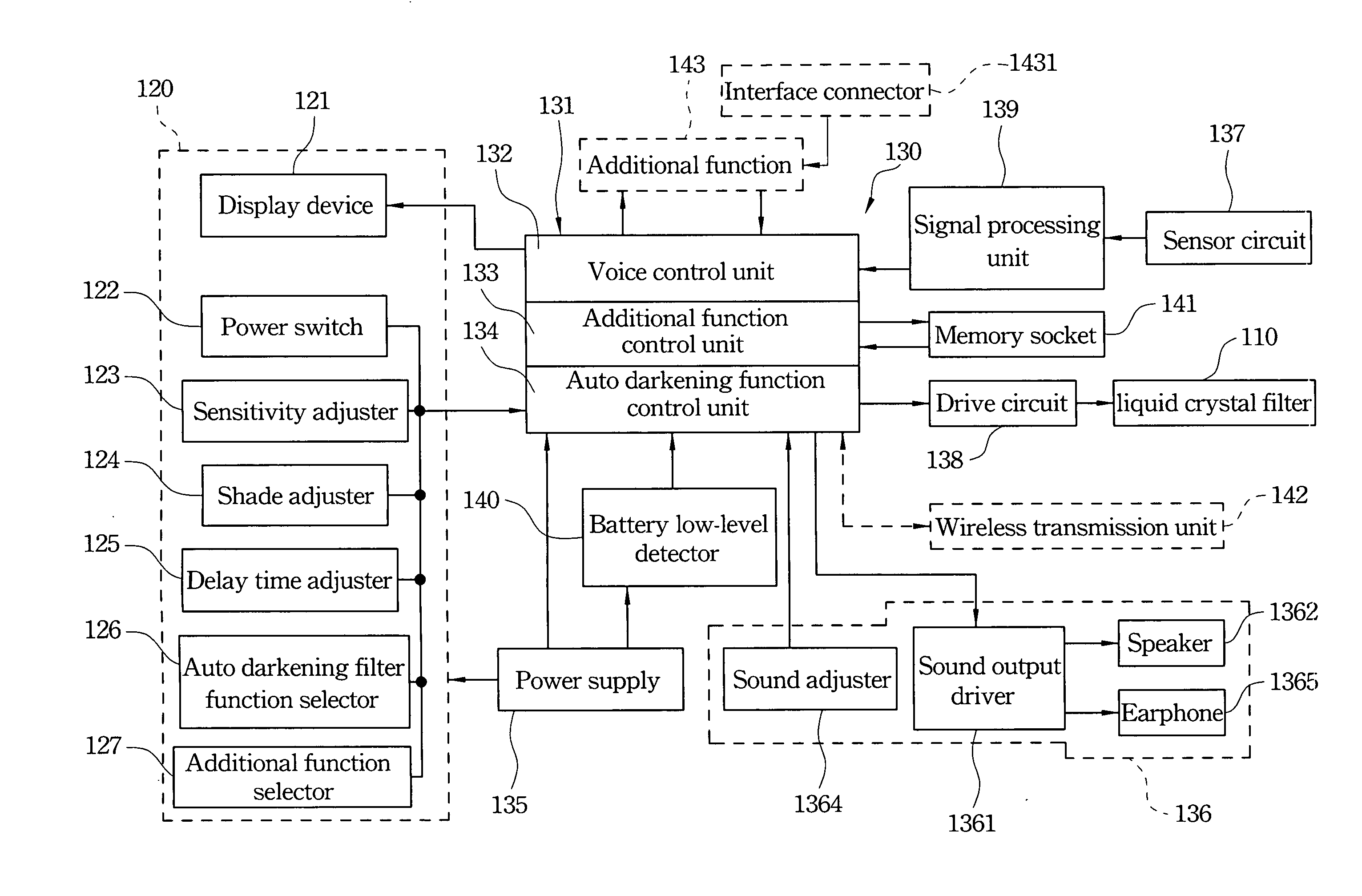
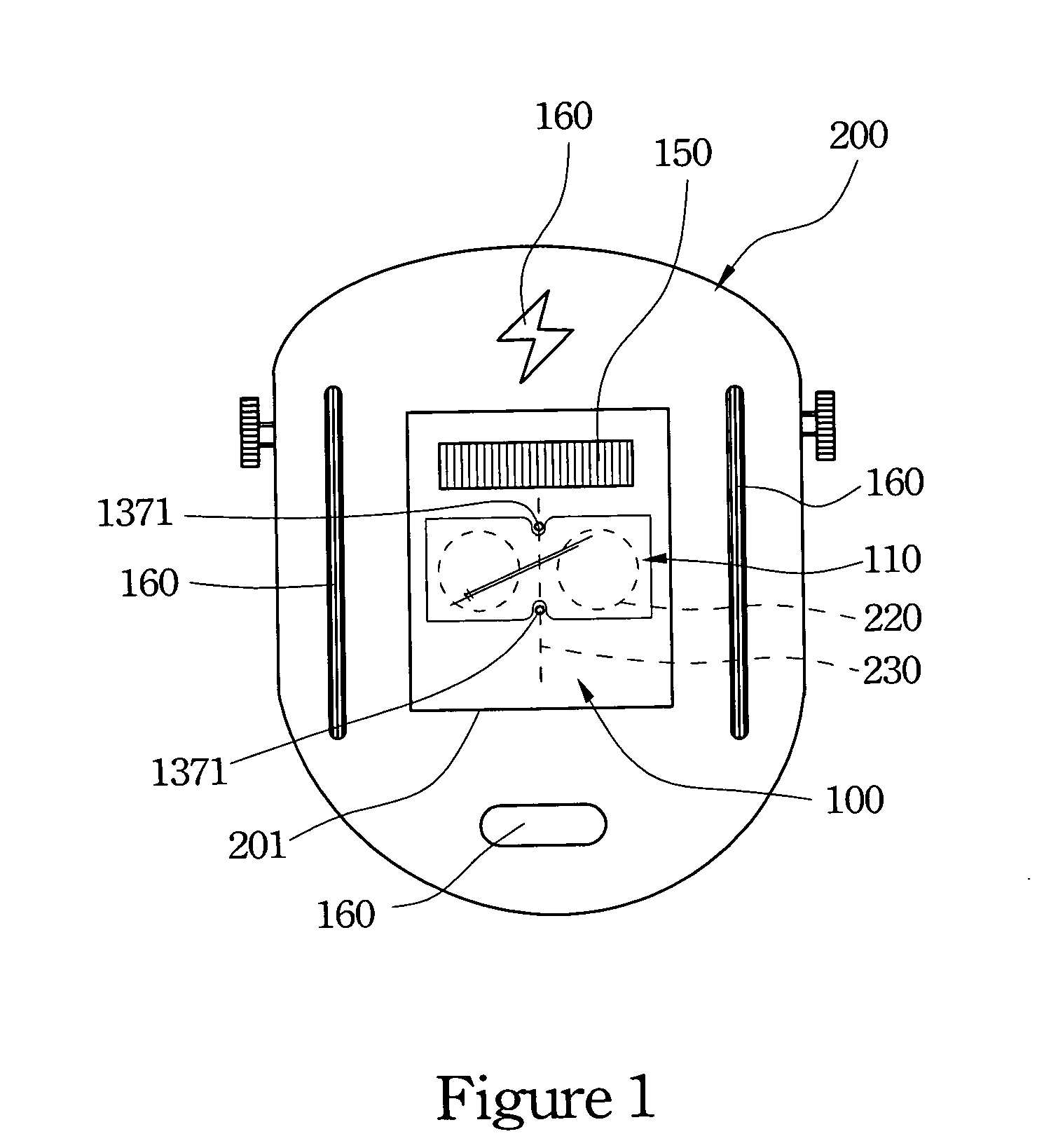
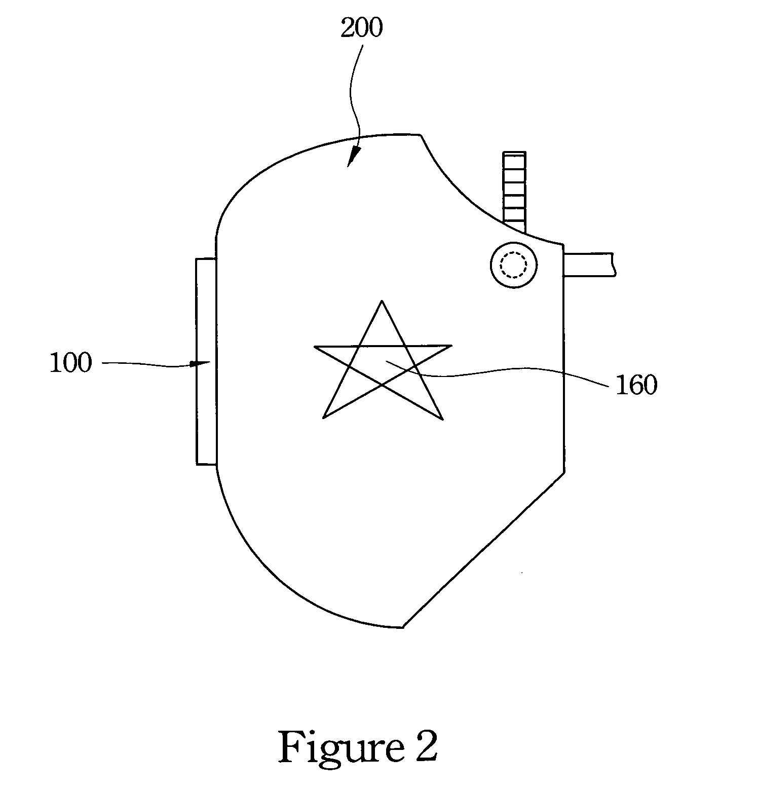
[0028]Refer to the figures from FIG. 1 to FIG. 5. FIG. 1 is the embodiment of an eye guard with voice indication. FIG. 2 is a side view of FIG. 1. FIG. 3 is a front view (external surface 101) of the body of the embodiment of the eye guard with voice indication. FIG. 4 is a back view (internal surface 102) of the body of the embodiment of the eye guard with voice indication. FIG. 5 is a block diagram of the embodiment of the eye guard with voice indication.
[0029]An eye guard with voice indication of the present invention includes an eye guard body 100, a filter 110, a touch panel 120, a display device 121 and a voice output device 130. The above components can be applied to the hand-held mask eye guard in FIG. 6 or the helmet eye guard in FIG. 1 and FIG. 2.
[0030]A shield 200 (mask or helmet) has an opening 201 and the body 100 is mounted in the opening 201 of the shield 200.
[0031]The filter 110 is mounted on the eye guard body 100 to resist infrared and ultraviolet rays and filter the light. In the embodiment, the filter 110 is a liquid crystal filter.
[0032]Refer to FIG. 3, FIG. 4 and FIG. 5. The touch panel 120 includes the display device 121 and a plurality of film keys, 122, 123, 124, 125, 126 and 127. The display device 121 is electrically connected with the voice output device 130 and is mounted inside the body 100 to display values of surrounding environmental parameters or information about the operating condition. The display device 121 is a light emitting flat panel display (FPD) and may be the plasma display panel (PDP), the vacuum fluorescent display (VFD), the field emission display (FED), the electro luminescent display (ELD), the electrochromic display (ECD), the electrophoretic display (EPID) or PLZT. The electro luminescent display (ELD) includes an organic light emitting display (OLED), a polymer light emitting display (PLED), organic electro luminescent display (OELD) or inorganic light emitting display.
[0033]The touch panel 120 is electrically connected with the voice output device 130 and the display device 121. The film keys of the touch panel 120 have a power switch 122, a sensitivity adjuster 123, a shade adjuster 124, a delay time adjuster 125, an auto darkening filter function selector 126 and an additional function selector 127. The auto darkening filter function selector 126 further includes darkening auto/manual adjuster or welding/cutting/grinding selector. The sensitivity adjuster 123, the shade adjuster 124 and the delay time adjuster 125 are controlled by the keys “Δ” and “∇” to adjust the function range.
[0034]Refer to FIG. 3 and FIG. 5. The voice output device 130 is mounted on a control circuit board 300 and includes a main controller 131, a power supply 135, a sound output controller 136, a sensor circuit 137, a drive circuit 138, a signal processing unit 139 and a battery low-level detector 140. The main controller 131 has a voice control unit 132, an additional function control unit 133 and an auto darkening function control unit 134. The drive circuit 138 is electrically connected between the main controller 131 and the filter 110. The signal processing unit 139 is electrically connected between the main controller 131 and the sensor circuit 137. The battery low-level detector 140 is electrically connected between the main controller 131 and the power supply 135.
[0035]The voice control unit 132 of the main controller 131 is a core control circuit for voice output in the voice output device 130. The voice control unit 132 has various language databases (Chinese, English or Japanese etc.) and controls the output of the audio signal.
[0036]Refer to FIG. 3, FIG. 4 and FIG. 5. The power supply 135 is used to provide the power for the main controller 131. In this embodiment, a solar cell 150 is used as the power supply 135 such that solar energy can be stored in two batteries 1351 to supply the power. In order to extend the supply period, a wire connector method can be applied for power supply. In the wire connection method, the transformer (not shown) is used to transform the power and a DC jack 1352 is used to charge the battery 1351 with the general power (110V/220V) or high volume battery when the capacitance of the battery 1351 is low.
[0037]The battery low-level detector 140 is used to detect the capacitance of the power supply 135. When the battery 1351 capacitance is low, the battery low-level detector 140 notices the voice control unit 132 of the main controller 131 to send the “low power” voice signal. Thus, the operator is notified when the battery need to be charged, changed, or connected to power lines.
[0038]Refer to FIG. 4 and FIG. 5. The sound output controller 136 includes a sound output driver 1361, a speaker 1362, an earphone socket 1363 and a sound adjuster 1364. Before the voice signal is outputted by the voice control unit 132, the voice signal is transformed into the sound frequency signal by the sound output driver 1361 and the voice in the voice control unit 132 is played by the speaker 1362. The voice can also be received by wearing an earphone 1365 when the earphone 1365 is plugged-in the earphone socket 1363. The sound adjuster 1364 has the control functions for the sound switch, volume and language settings such that the operator can turn on/off the sound, adjust the volume and change various language.
[0039]Refer to FIG. 1, FIG. 3, FIG. 5 and FIG. 6. The sensor circuit 137 is used to detect the external circumstance with the sensor 1371. Furthermore, the sensors 1371 can be two sensors exposed on the external surface 101 and defined in the supposed centerline 230 of the filter 110. The sensors 1371 can also be four sensors arranged along the centerline 230 and the opposite flanks of the filter 110 as shown in FIG. 3. When the circumstance value is detected by the sensors 1371, the circumstance value is processed by the signal processing unit 139 to amplify, rectify and filter. After the voice control unit 131 procedure, a voice signal is outputted by the speaker 1362 (or the earphone 1365) of the sound output controller 136 when the circumstance is changed or different from the initial setting. Thus, the warning effect is obtained by the notification voice of the circumstance value or operating condition information. Furthermore, the two sensors 1371 exposed on the external surface 101 and defined in the supposed centerline 230 of the filter 110 can be used to detect the external welding light. The other two sensors 1371 arranged in the opposite flanks of the filter 110 can be used to detect the temperature and the moisture.
[0040]Refer to FIG. 4 and FIG. 5. The voice output device 130 further includes a memory socket 141, a wireless transmission unit 142 and an additional function 143. The memory socket 141 is used to access the sound data and audio data of various memory cards to update or add the voice data. The various memory cards can be the CF, SD, xD, MiniSD, MicroSD, MMC, RS-MMC, MS Pro Duo and T-Fish. The wireless transmission unit 142, a bluetooth or an infrared system, is used to transmit other functions. In FIG. 5, an interface connector 1431 is set in the body 100 to connect with the electrical devices to provide the additional function 143. The functions of the connected electrical devices can be partially or completely contained to the eye guard with voice indication by the IEEE-1394, USB1.1/2.0 or RS-232/RS-242 interfaces. The electrical devices can be GPS, PDA, phone, digital camera, temperature/moisture detector, radio, MP3/MP4 player, TV, clock/alarm, recorder, digital calendar or game.
[0041]Refer to FIG. 1 and FIG. 2. The eye guard with voice indication of the present invention further includes multiple assisted displays 160 exposed on the shield 200 to provide warning effects. The assisted displays 160 are light emitting flat panel display (FPD) configured in the form of the word, numeral, pattern, line, geometric picture or monochromatic/polychromatic/color pattern. The above display forms can be static or dynamic. Therefore, the assisted displays 160 exposed on the shield 200 are provided for warning effects when the user operates in a dark environment or at night. Additionally, using the assisted displays 160 with various numerals or patterns may identify and classify different operator groups.
[0042]The conventional eye guard containing light emitting diode (LED) has the drawback of that complex information cannot be shown and the display effect is not obvious. In addition, the conventional eye guard containing liquid crystal display (LCD) has the drawback that the LCD cannot self illuminate except by adding the back-light module or color filter and only provides visual identification effects. Consequently, the eye guard with voice indication of the present invention has the following efficiencies:
[0043]1. The eye guard with voice indication of the present invention co-ordinates with the voice output function and the eye guard function. The outputted voice indication is provided for the operators to inform about different circumstances and operation conditions during welding process. This method can improve that the operators only depend on the instincts or the visual images of the various circumstance information and operation conditions to weld. Thus, the operators can concentrate on operating with less interference.
[0044]2. The light emitting flat panel display (FPD) can be applied to the display device 121 and the assisted display 160 to warn the surrounding operators to notice the welding light.
[0045]3. Because of the self-luminance feature of the flat panel display, the power consumption can be reduced and the viewing angle limitation problem can also be solved. Furthermore, the shade, the contrast and the reaction speed can also be enhanced by using the flat panel display (FPD).
[0046]4. The touch panel is in the form of the film such that the hardness is lessened and the waterproof effect is enhanced.
[0047]5. The display device 121 of the present invention can be mounted in the eye guard body 100 and can also be mounted outside the eye guard body 100 by a power wire 210. Hence, the sound warning and the visual display are provided simultaneously during the operation with this eye guard with voice indication. As a result, the diverse information can be clearly noticed to prevent the operators from injury and boost the security.
[0048]6. The conventional sensors are inappropriately moved to be prevented from being covered by other objects. In this way, the sensor cannot normally detect the surrounding circumstance such that the user's eye would be injured. The sensors of the present invention are exposed on the external surface 101 and defined in the supposed centerline 230 of the filter 110. Thus, the problem caused by the arrangement of the conventional sensors can be solved.
[0049]Although the present invention has been described in considerable detail with reference to certain preferred embodiments thereof, other embodiments are possible. Therefore, their spirit and scope of the appended claims should no be limited to the description of the preferred embodiments container herein.
[0050]It will be apparent to those skilled in the art that various modifications and variations can be made to the structure of the present invention without departing from the scope or spirit of the invention. In view of the foregoing, it is intended that the present invention cover modifications and variations of this invention provided they fall within the scope of the following claims and their equivalents.