
Composite heating element with an integrated switch

a technology of heating element and integrated switch, which is applied in the direction of heating element shape, ohmic resistance heating, etc., can solve the problems of large battery size, affecting the use of jackets, so as to reduce the size of the battery and improve the use flexibility, excellent battery power conservation, and excellent flexibility in use

Inactive Publication Date: 2008-04-10
T INK INC
View PDF27 Cites 91 Cited by
  • Summary
  • Abstract
  • Description
  • Claims
  • Application Information

AI Technical Summary

Benefits of technology

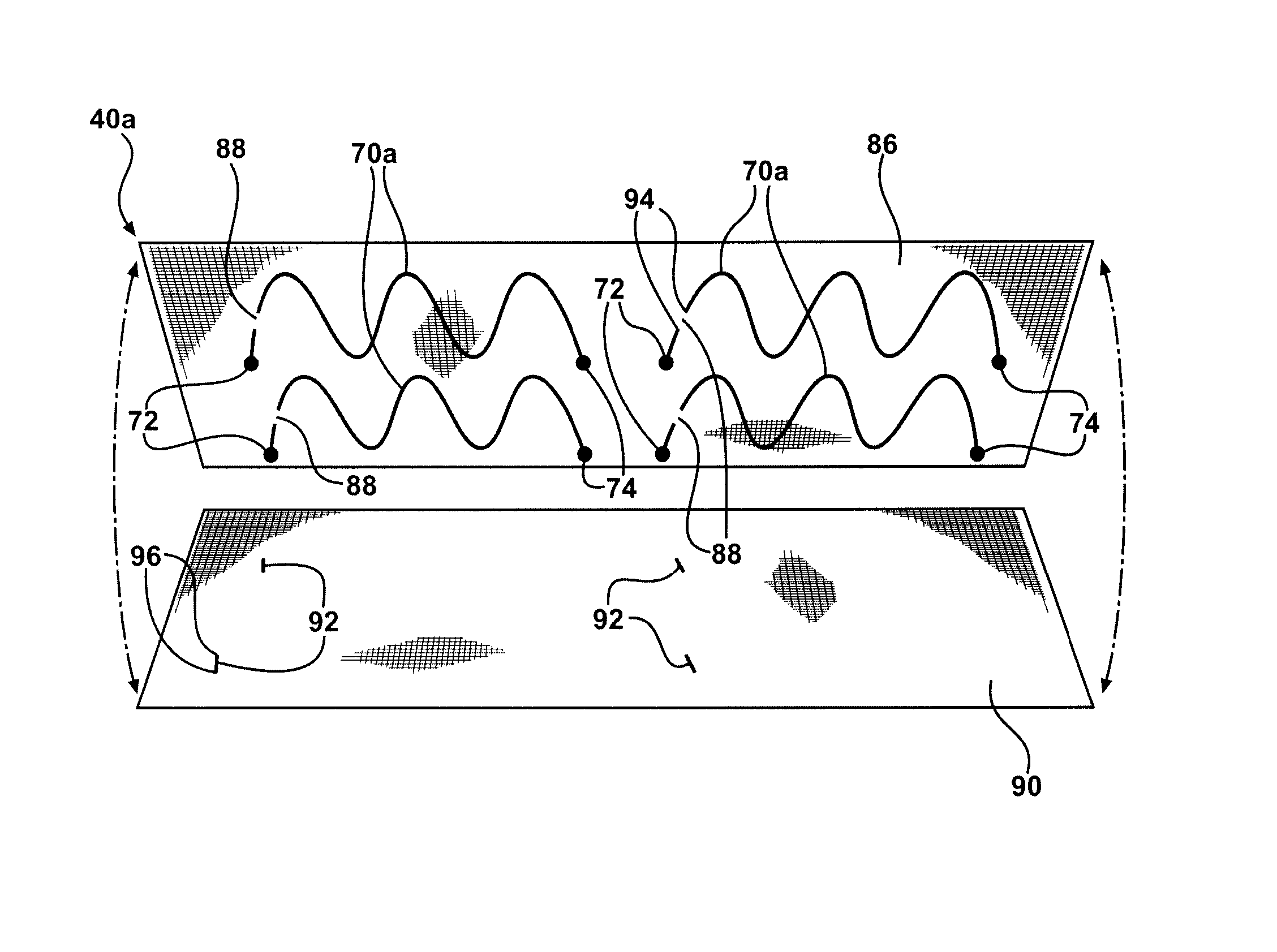
[0009] The discontinuous circuit of the composite heating element of the present invention allows for excellent conservation of battery power, reduction of battery size, and flexibility in using a plurality of the composite heating elements and locations thereof. The discontinuous circuit of the composite heating element also allows for selectively heating one or more heating zones, provides uniform and consistent heating of one or more heating zones, and allows for excellent flexibility in using various power sources and locations thereof.

Problems solved by technology

Larger batteries are heavy, bulky, aesthetically displeasing, functionally awkward, and may be potentially hazardous to the wearer of the article.
Further, the wearer is unaware of how much heating time remains for each zone, i.e., how much power each individual battery can still provide each zone over extended use.
A wearer of the jacket is, however, not able to control the oscillator chip, which may cycle in a manner that is uncomfortable for the wearer.
For example, when the heating element is “off”, the wearer may quickly become cold during this down time, such as while the wearer is skiing.
Further, devices such as the oscillator chip increases cost of the articles that utilize them and such devices can fail over time.
The failures can occur with normal use over time or with exposure to impact or moisture, which requires repair or replacement of the device, if not replacement of the entire article.

Method used


Image

  • Composite heating element with an integrated switch
  • Composite heating element with an integrated switch
  • Composite heating element with an integrated switch

Examples


Embodiment Construction

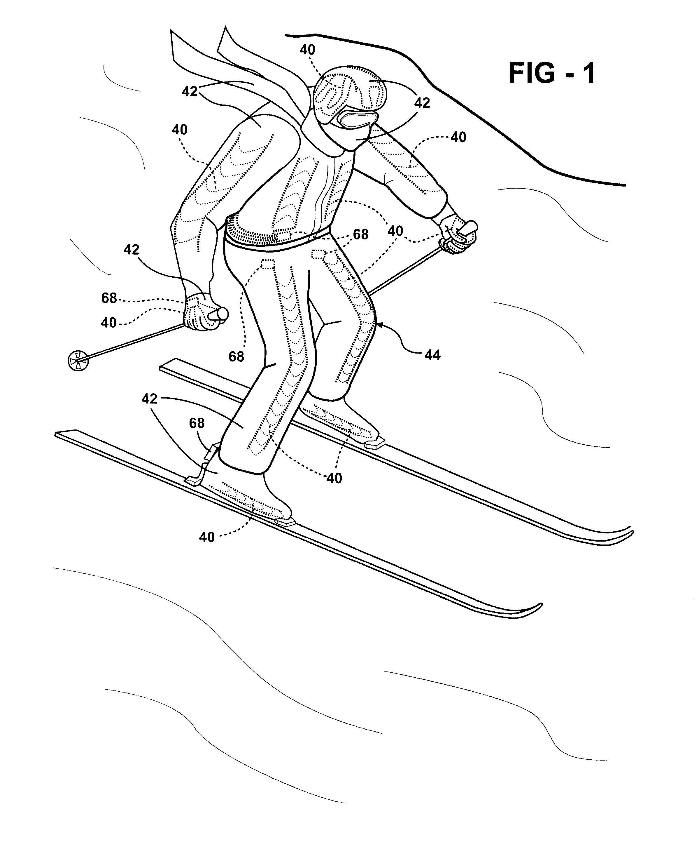
[0046] The present invention provides heating elements suitable for heating an article when activated by a power source. The article may be any type of article known in the art. Non-limiting examples of suitable articles, for purposes of the present invention, include, but are not limited to, jackets, vests, shirts, pants, shorts, bibs, coveralls, seats, mattresses, mattress-pads, pads, sleeping-bags, shoes, boots, ski-boots, snowboard-boots, waders, socks, mittens, gloves, hats, scarves, headbands, ear-muffs, underwear, bandages, neck-gators, face-masks, balaclavas, wetsuits, drysuits, hoods, helmets, wraps, bandages, sheets, blankets, pillows, pillow-cases, comforters, duvet-covers, bags, containers, carpet, flooring, wallboard, and ceiling tile. The composite heating elements are especially suitable for articles worn, such as jackets, gloves, hats, boots, wraps, and bandages. The composite heating elements are also especially suitable for articles laid upon, such as mattresses, b...


PUM


Abstract

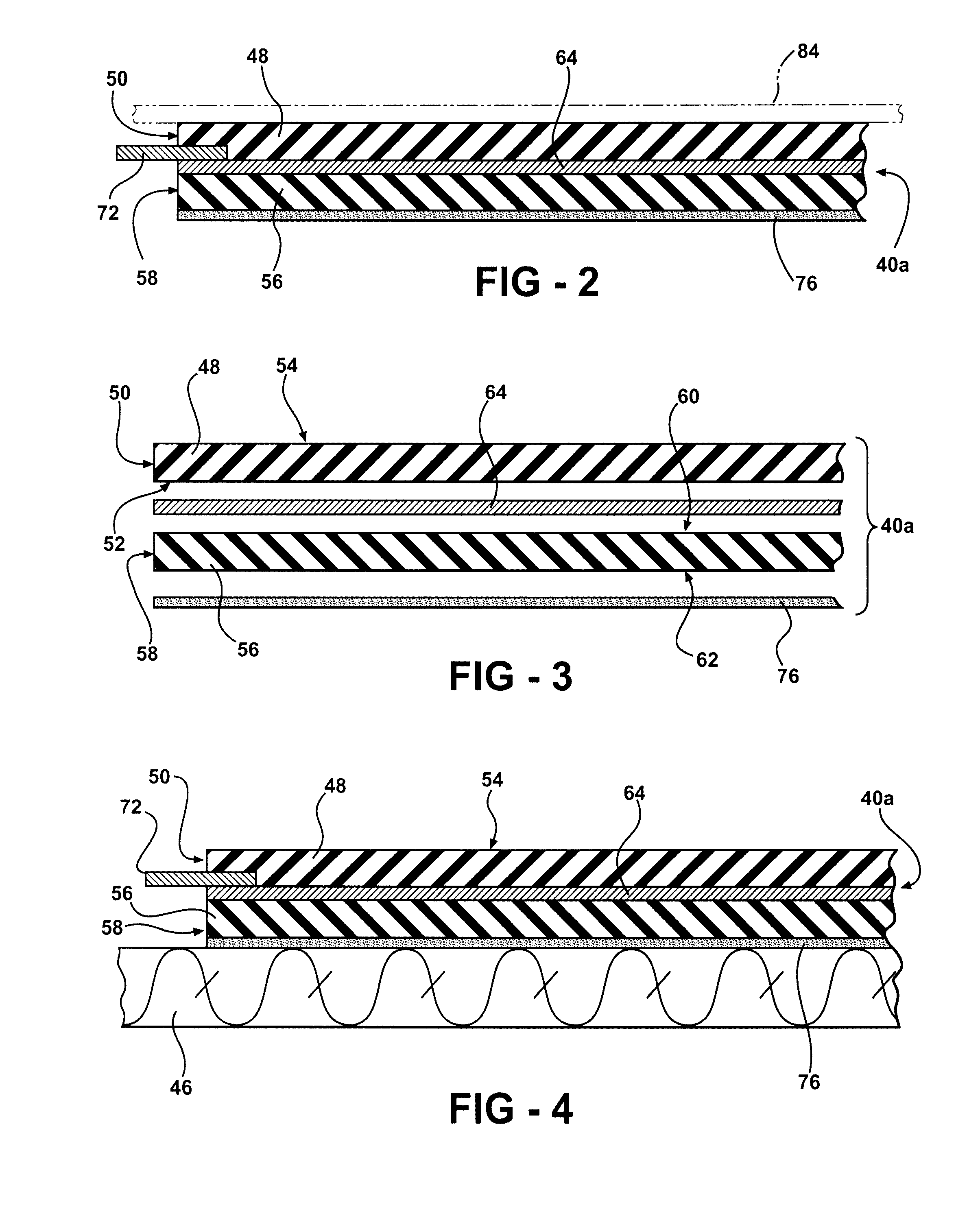
The present invention provides a composite heating element suitable for heating an article when activated by a power source. The composite heating element comprises a first backing layer and a discontinuous circuit formed of a conductive material disposed on the first backing layer. The discontinuous circuit has terminal ends for electrical connection with the power source and defines at least one gap between the terminal ends. The composite article further comprises a second backing layer spaced from the first backing layer. A trace formed of a conductive material is disposed on the second backing layer. The trace is aligned with the at least one gap for forming a complete circuit when the first and second backing layers at least partially abut each other with the trace extending across the gap and contacting the discontinuous circuit.

Description

CROSS REFERENCE TO RELATED APPLICATIONS [0001] This application claims the benefit of U.S. Provisional Patent Application Ser. No. 60 / 849,418 filed on Oct. 4, 2006 and incorporated herewith in its entirety.FIELD OF THE INVENTION [0002] The present invention generally relates to a composite heating element, and, more specifically, to a composite heating element suitable for heating an article when activated by a power source, and to an article including the composite heating element. DESCRIPTION OF THE RELATED ART [0003] Articles having heating elements to heat a wearer of the article, such as heated jackets and vests, are well known in the art. Many of these articles have a heating element to heat one zone of the article, e.g. a back side of the article, while other articles have two or more heating elements to heat two or more zones of the article, e.g. a left and right side of the article. The heating elements are generally powered by one or more batteries to power the heating ele...

Claims


Application Information

Patent Timeline
IPC IPC(8): H05B3/06
CPCA43B7/04H05B3/342H05B2203/003H05B2203/005H05B2203/011H05B2214/04H05B2203/017H05B2203/026H05B2203/029H05B2203/036H05B2203/013A43B3/35
Inventor KAISERMAN, TERRANCEGENTILE, JOHNGENTILE, ANTHONY
Owner T INK INC
Learn More