Traveling Mechanism for Agricultural Machines and Off-Road Vehicles Having an Endless Belt -Band Traveling Gear and a Corresponding Belt-Band Traveling Gear

a technology of agricultural machines and off-road vehicles, which is applied in the direction of vehicles, vehicle components, suspensions, etc., can solve the problems of reduced tire load, inability to support the vehicle, and inability to accept high soil compaction, so as to improve the driving comfort, increase the tilt resistance, and improve the effect of traction

Inactive Publication Date: 2008-04-10
DEERE & CO
View PDF15 Cites 32 Cited by
  • Summary
  • Abstract
  • Description
  • Claims
  • Application Information

AI Technical Summary

Benefits of technology

[0030] In addition, the belt-band traveling gear according to the present invention enables a very easily realizable, automatically controllable or manually adjustable slope compensation since a certain inclination can be compensated during travel uphill or downhill by a corresponding pressurization of the traveling gear supporting cyl

Problems solved by technology

These high surface pressures can lead to an impermissibly high soil compaction especially in wet farmlands.
Even a reduced internal pressure of tires cannot change much about this problem since in the case of a clearly reduced tire pressure as would be desirable per se for traveling on soft or wet farmlands, the load on the tires is reduced as a result of which the weight of the vehicle can no longer be supported.
The typical disadvantage of these rigidly mounted deflection rollers is a very limited driving and rolling comfort as compared to a wheeled traveling mechanism, particularly during on-road operation.
An addi

Method used


Image

  • Traveling Mechanism for Agricultural Machines and Off-Road Vehicles Having an Endless Belt -Band Traveling Gear and a Corresponding Belt-Band Traveling Gear
  • Traveling Mechanism for Agricultural Machines and Off-Road Vehicles Having an Endless Belt -Band Traveling Gear and a Corresponding Belt-Band Traveling Gear
  • Traveling Mechanism for Agricultural Machines and Off-Road Vehicles Having an Endless Belt -Band Traveling Gear and a Corresponding Belt-Band Traveling Gear

Examples


Embodiment Construction

[0032] The present invention shall now be explained in detail on the basis of a preferred exemplary embodiment with reference to the attached drawings. The example serves for illustrating the invention. However, it is by no means to be construed as a restriction of the invention. Identical parts and parts performing identical functions are denoted by the same reference numerals; repeat explanations have been avoided to some extent.

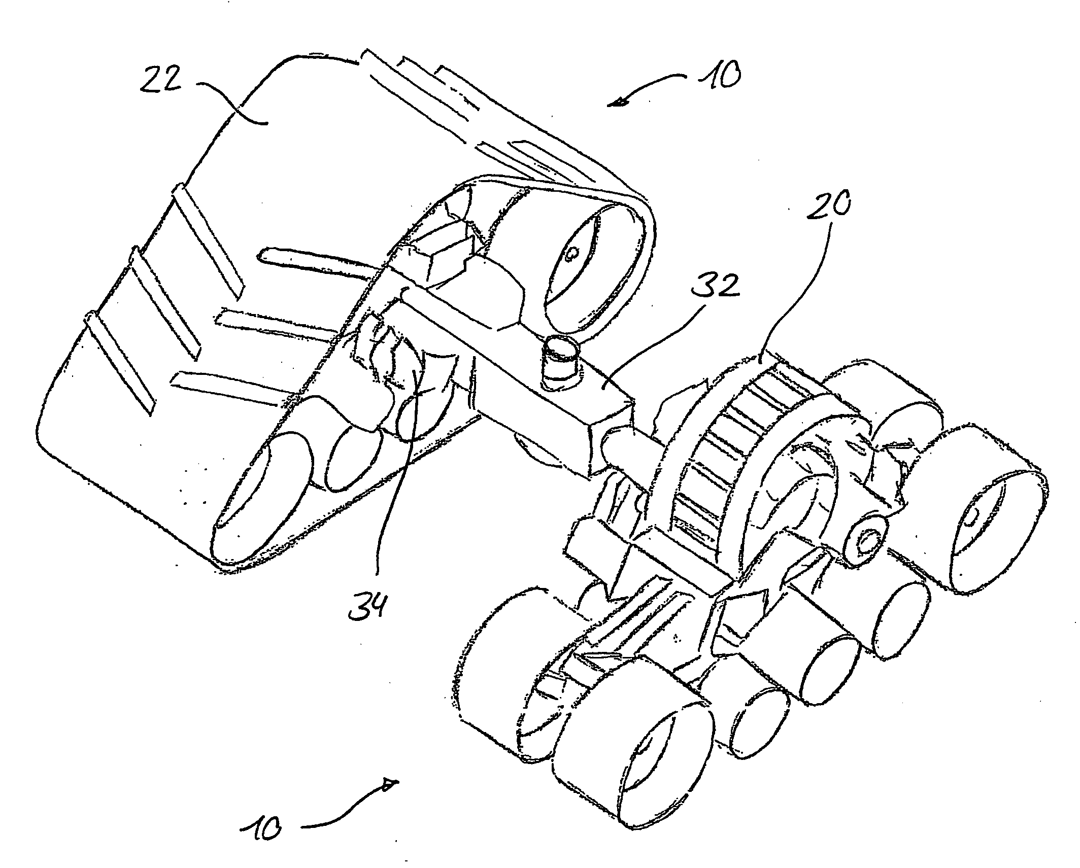
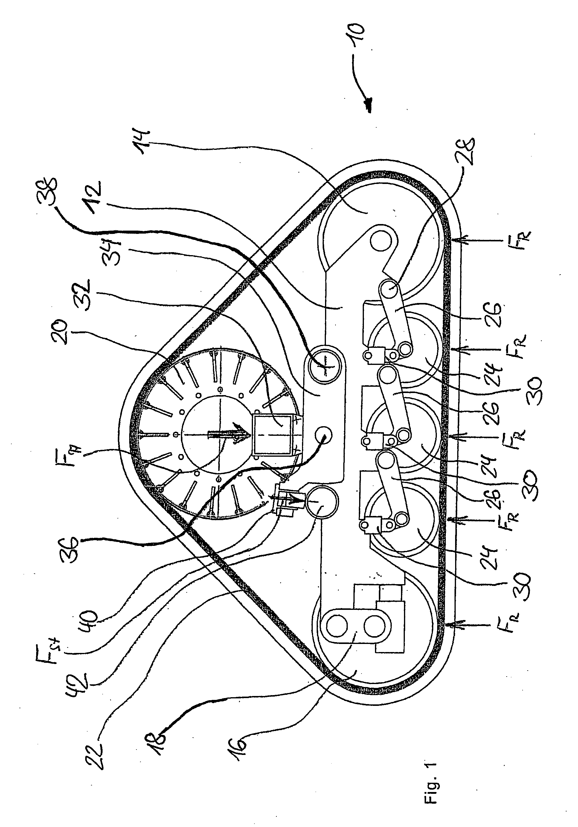
[0033]FIG. 1 shows a schematic drawing of a basic structure of a variant of the belt-band traveling gear according to the present invention.

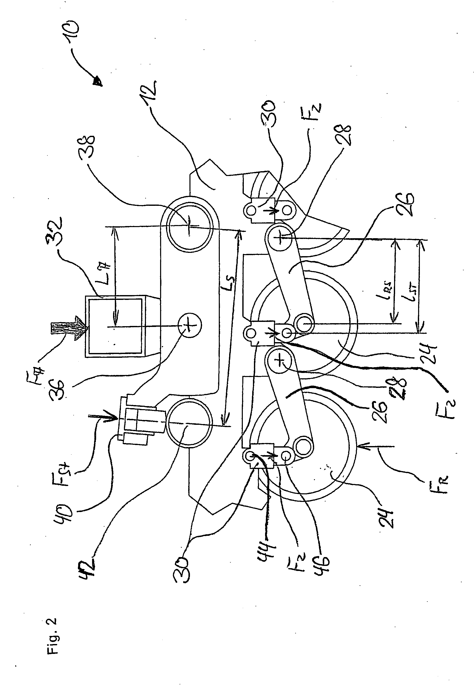
[0034]FIG. 2 shows a schematic drawing of a section of the basic structure of the belt-band traveling gear shown in FIG. 1.

[0035]FIG. 3 shows a schematic sectional view of the belt-band traveling gear.

[0036]FIG. 4 shows a lateral view of another variant of the belt-band traveling gear.

[0037]FIG. 5 shows a possible structure of the piping for connecting the elements of the belt-band traveling gear based on a schema...


PUM


Abstract

The invention relates to a spring-suspended, bearing force-optimized belt-band traveling gear (10) for ground vehicles, particularly for self-propelled agricultural machines and other off-road vehicles, comprising at least two outer deflection rollers (14, 15, 16, 17) over whose periphery an endless belt-band (22) rolls off, and at least one supporting roller (24) for supporting the belt-band section, which is in contact with the ground, between both deflection rollers (14, 15, 16, 17). A bogie truck (12, 13), in which the at least two deflection rollers (14, 15, 16, 17) are mounted in a manner that enables them to rotate, is supported against a body frame of the vehicle by means of a first fluidic suspension unit and/or damping unit. The at least one supporting roller (24) is supported on the bogie truck (12, 13) by means of a second fluidic suspension unit and/or damping unit. A fluidic coupling of the suspension units and/or damping units of the bogie truck (12, 13) is provided against the vehicle frame and the at least one supporting roller (24) mounted on the bogie truck (12, 13).

Description

[0001] The present invention relates to a traveling mechanism for agricultural machines and off-road vehicles having an endless belt-band traveling gear. The invention further relates to a belt-band traveling gear, particularly a spring-mounted, belt-band traveling gear with optimum bearing strength specifications, said belt-band traveling gear being suitable inter alia for self-propelled agricultural machines and other off-road vehicles. Furthermore, the invention relates to a ground vehicle having a spring-mounted belt-band traveling gear with optimum bearing strength specifications. STATE OF THE ART [0002] Ground vehicles used in agriculture usually comprise pneumatic tires, which create the interface to the ground. The tires have to support the weight of the vehicle on the one hand while providing the required traction on the other. In very heavy vehicles, for example, in self-propelled harvesters, relatively high surface pressures result below the contact surfaces in spite of v...

Claims


Application Information

Patent Timeline
IPC IPC(8): B62D55/112
CPCB62D55/112B62D55/14B62D55/1125B60G2206/011
Inventor RAINER, JOHANN
Owner DEERE & CO
Why Eureka
Try Eureka