Grounding fault transient current generator

A transient current and ground fault technology, which is applied in high-voltage/high-current switches, transformer/reactor installation/support/suspension, circuits, etc., can solve problems such as prone to high-voltage oscillations, burned voltage transformers, and easy shaking. Achieve the effects of improving reliability and safety, improving overall stability, and facilitating installation and operation

Pending Publication Date: 2021-04-16
ANHUI KAIMIN ELECTRIC POWER TECH
View PDF0 Cites 0 Cited by
  • Summary
  • Abstract
  • Description
  • Claims
  • Application Information

AI Technical Summary

Problems solved by technology

However, according to years of operating experience and the development of medium-voltage power transmission and distribution systems in recent years, the non-direct grounding of the neutral point has also brought some problems to the medium-voltage power transmission and distribution system: the non-direct grounding of the neutral point is easy Occurrence of high-voltage oscillations, resulting in various overvoltages
This current is often much greater than the rated current of the voltage transformer, which will cause the iron core of the transformer to saturate, and the primary side current will increase sharply, blowing the fuse of the voltage transformer, or even burning the voltage transformer; it is difficult to determine the branch circuit where

Method used


Image

  • Grounding fault transient current generator
  • Grounding fault transient current generator

Examples


Embodiment Construction

[0016] In order to make the technical means, creative features, goals and effects achieved by the present invention easy to understand, the present invention will be further described below in conjunction with specific embodiments.

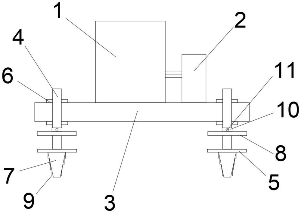
[0017] Such as Figure 1-2 As shown, a ground fault transient current generator includes a grounding transformer 1, the grounding transformer 1 is connected to the system bus, the neutral point of the grounding transformer 1 is connected to a monostable switch 2, and the monostable The switch 2 is connected to the ground, the grounding transformer 1 and the monostable switch 2 are fixed on the installation base plate 3, and the four corners of the installation base plate 3 are threaded into the insertion rod 4, and the insertion rods 4 are located on both sides of the installation base plate 3 The outer ring is threadedly connected to the lock nut 6, the lower end of the insertion rod 4 is fixedly connected to the deep buried block 7, the upper en...


PUM


Abstract

The invention discloses a grounding fault transient current generator, which comprises a grounding transformer, wherein the grounding transformer is connected with a system bus, a neutral point is led out of the grounding transformer to be connected with a monostable switch, the monostable switch is connected with the ground, the grounding transformer and the monostable switch are both fixed to a mounting bottom plate, four corners of the mounting bottom plate are in threaded connection with inserting rods, the outer rings, which are located on two sides of the mounting bottom plate, of the inserting rods are in threaded connection with locking nuts, the lower ends of the inserting rods are fixedly connected with deeply-buried blocks, the upper ends of the deeply-buried blocks are fixedly connected with lower sleeve plates, and outer rings of the inserting rods sleeve upper sleeve plates. According to the invention, the neutral point led out of the grounding transformer is connected with the monostable switch, when a system branch breaks down, the monostable switch is triggered, the reliability and safety of system power supply are improved, the manufacturing cost is low, and installation and operation are convenient. In addition, the deeply-buried blocks connected with the lower ends of the inserting rods and the lower sleeve plates and the upper sleeve plates which are connected with the inserting rods are deeply buried into the ground, so that the overall stability and the inclination resistance are improved.

Description

technical field [0001] The invention relates to the technical field of grounding safety electricity utilization, in particular to a ground fault transient current generator. Background technique [0002] In my country's 3-35KV medium-voltage transmission and distribution systems, most of them adopt the method of not directly grounding the neutral point, that is, the neutral point is not grounded or grounded through the arc suppression coil. The neutral point is not directly grounded. In the state of single-phase grounding, the system line voltage can still maintain three-phase symmetry without affecting the normal operation of electrical equipment. Therefore, the power supply reliability of the power transmission and distribution system using the neutral point not directly grounded method is much higher than that of the neutral point directly grounded power transmission and distribution system. This is the biggest advantage of the neutral point not directly grounded method, ...

Claims


Application Information

Patent Timeline
IPC IPC(8): H02H9/08H01F27/06H01H9/02H01H33/66
Inventor 项贤文
Owner ANHUI KAIMIN ELECTRIC POWER TECH
Why Eureka
Try Eureka