
Dust removal apparatus of photographing apparatus

Inactive Publication Date: 2008-04-10
PENTAX RICOH IMAGING CO LTD
View PDF11 Cites 9 Cited by
  • Summary
  • Abstract
  • Description
  • Claims
  • Application Information

AI Technical Summary

Benefits of technology

[0007]Therefore, an object of the present invention is to provide a dust removal apparatus that reduces damage the mechanism during the dust removal operation and removes the dust more efficiently.

Problems solved by technology

However, the movable unit 30a etc. may sustain damage caused by heat and shock from continuous impact between the movable unit and the boundary of the range of movement of the movable unit.

Method used


Image

  • Dust removal apparatus of photographing apparatus
  • Dust removal apparatus of photographing apparatus
  • Dust removal apparatus of photographing apparatus

Examples


Embodiment Construction

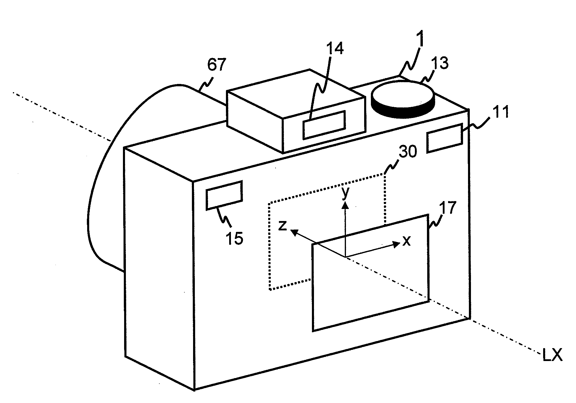
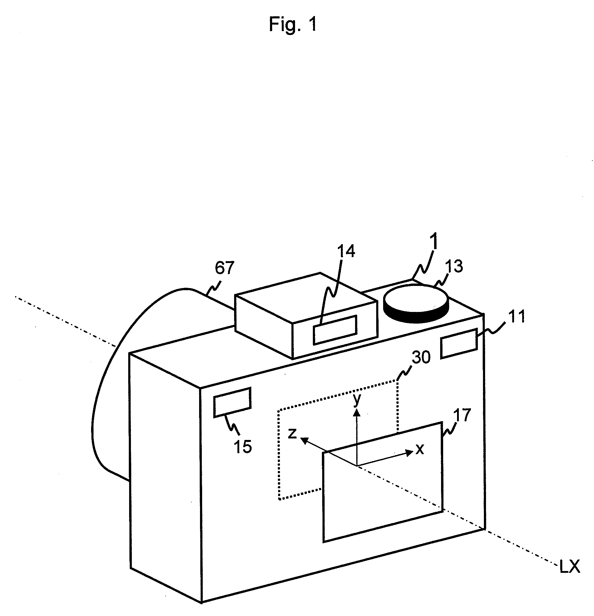
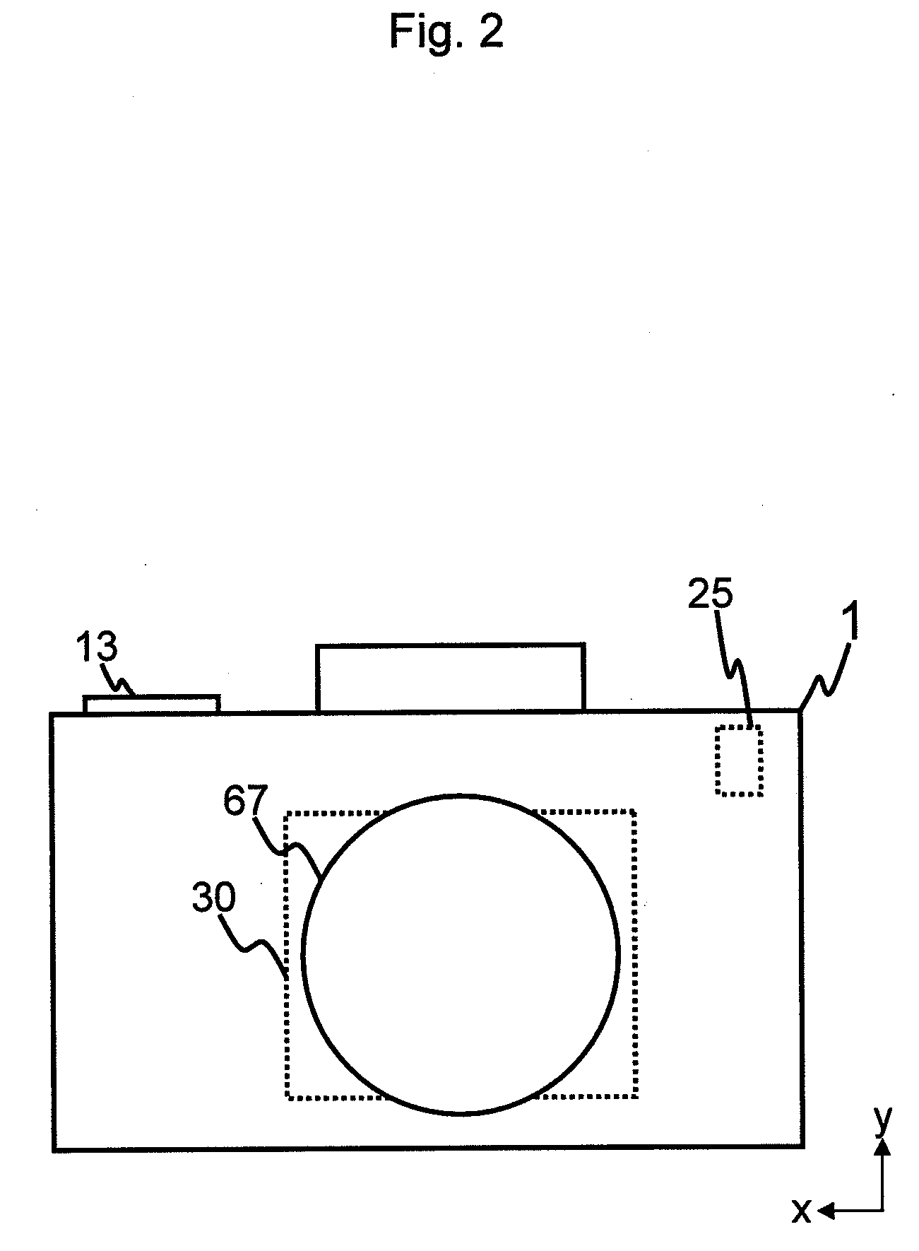
[0020]The present invention is described below with reference to the embodiment shown in the drawings. In the embodiment, the photographing apparatus 1 is a digital camera. A photographing optical system, such as a camera lens 67 etc., that captures (images) an optical image on a photographing surface of the imaging device of the photographing apparatus 1 has an optical axis LX.

[0021]In order to explain the orientation of the embodiment, a first direction x, a second direction y, and a third direction z are defined (see FIG. 1). The first direction x is perpendicular to the optical axis LX. The second direction y is perpendicular to the optical axis LX and the first direction x. The third direction z is parallel to the optical axis LX and perpendicular to both the first direction x and the second direction y.

[0022]The imaging and the dust removal part (the dust removal apparatus) of the photographing apparatus 1 comprises a PON button 11, a PON switch 11a, a photometric switch 12a, ...


PUM


Abstract

A dust removal apparatus of a photographing apparatus comprises a movable unit and a controller. The movable unit has an imaging device and is movable. The controller strikes the movable unit against a boundary of a range of movement of the movable unit as a dust removal operation. The controller counts the number of times of the dust removal operation, measures an elapsed time from the point when counting the number of times of the dust removal operation commences. When the elapsed time is less than or equal to a time period and the number of times of the dust removal operation is equal to or greater than a predetermined number of times, the controller halts the dust removal operation until a predetermined time period has elapsed.

Description

BACKGROUND OF THE INVENTION[0001]1. Field of the Invention[0002]The present invention relates to a dust removal apparatus of a photographing apparatus, and in particular to restrain the damage to the mechanism caused by the dust removal operation.[0003]2. Description of the Related Art[0004]A dust removal apparatus of a photographing apparatus, that removes the dust on the imaging device and the cover such as the low-pass filter, is proposed.[0005]Japanese unexamined patent publication (KOKAI) No. 2005-340988 discloses a dust removal apparatus that strikes the movable unit including the imaging device against the boundary of the range of movement of the movable unit so that the shock of impact will remove the dust on the imaging device and the cover etc.[0006]However, the movable unit 30a etc. may sustain damage caused by heat and shock from continuous impact between the movable unit and the boundary of the range of movement of the movable unit.SUMMARY OF THE INVENTION[0007]Therefor...

Claims


Application Information

Patent Timeline
IPC IPC(8): H04N5/225
CPCH04N5/232H04N5/2171G02B27/0006H04N23/811H04N23/55H04N23/60
Inventor UENAKA, YUKIOIWAMOTO, SHIGERU
Owner PENTAX RICOH IMAGING CO LTD
Learn More