Damper and Vacuum Pump

a vacuum pump and damper technology, applied in the field of dampers, can solve the problems of affecting the performance of the system, requiring a certain degree of rigidity, and causing vibration caused by the oscillation of the shaft, so as to achieve the effect of reducing vibrations on a particular frequency band

Active Publication Date: 2008-04-10
EDWARDS JAPAN
View PDF6 Cites 14 Cited by
  • Summary
  • Abstract
  • Description
  • Claims
  • Application Information

AI Technical Summary

Benefits of technology

[0025] Accordingly, an object of the present invention is to provide a damper capable of reducing vibrations on a particular frequency band while the degree of freedom (flexibility) of installation posture of a vacuum pump is maintained, and a vacuum pump.
[0036] According to the present invention, the notch filter type vibration isolating structure is formed by using the first vibration absorbing member provided with the spring element having a spring constant k and the mass element having a mass m and the second vibration absorbing member provided with the spring element having a spring constant K and the damping element having a viscosity damping coefficient C, by which vibrations on a particular frequency band can be reduced properly.

Problems solved by technology

Also, in the case where the rotor is not balanced completely, vibrations caused by the oscillation of shaft may also be produced.
If such vibrations produced in the vacuum pump propagate to the vacuum system side, the performance of the system may be hindered.
Therefore, the damper requires a certain degree of high rigidity.
That is to say, there is also a limit in decreasing the damping coefficient of damper.
However, in the case where the natural frequency of the whole of the damper system is reduced by decreasing the damping coefficient, the stability of vacuum pump at the time when the vacuum pump is subjected to disturbance may be impaired.
Also, in the case where the natural frequency of the whole of the damper system is reduced by decreasing the rigidity of damper, the vacuum pump may become incapable of being supported stably when the vacuum pump is installed in an upside down posture (the suction port is directed downward) or in a horizontal posture (directed horizontally).
If a trouble such as deflection or tilt occurs, the degree of freedom (flexibility) of installation posture of vacuum pump is restricted.

Method used


Image

  • Damper and Vacuum Pump
  • Damper and Vacuum Pump
  • Damper and Vacuum Pump

Examples


Embodiment Construction

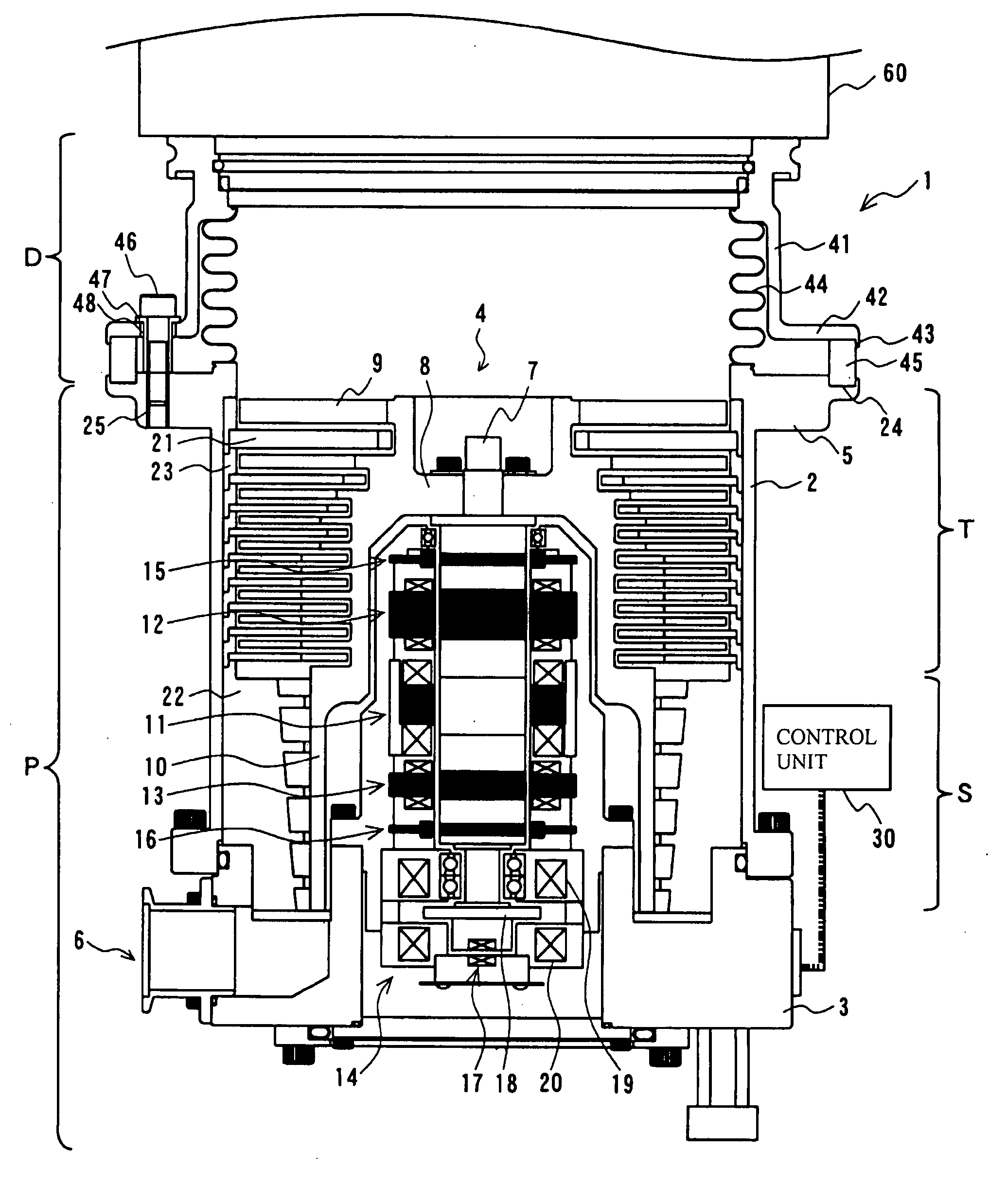
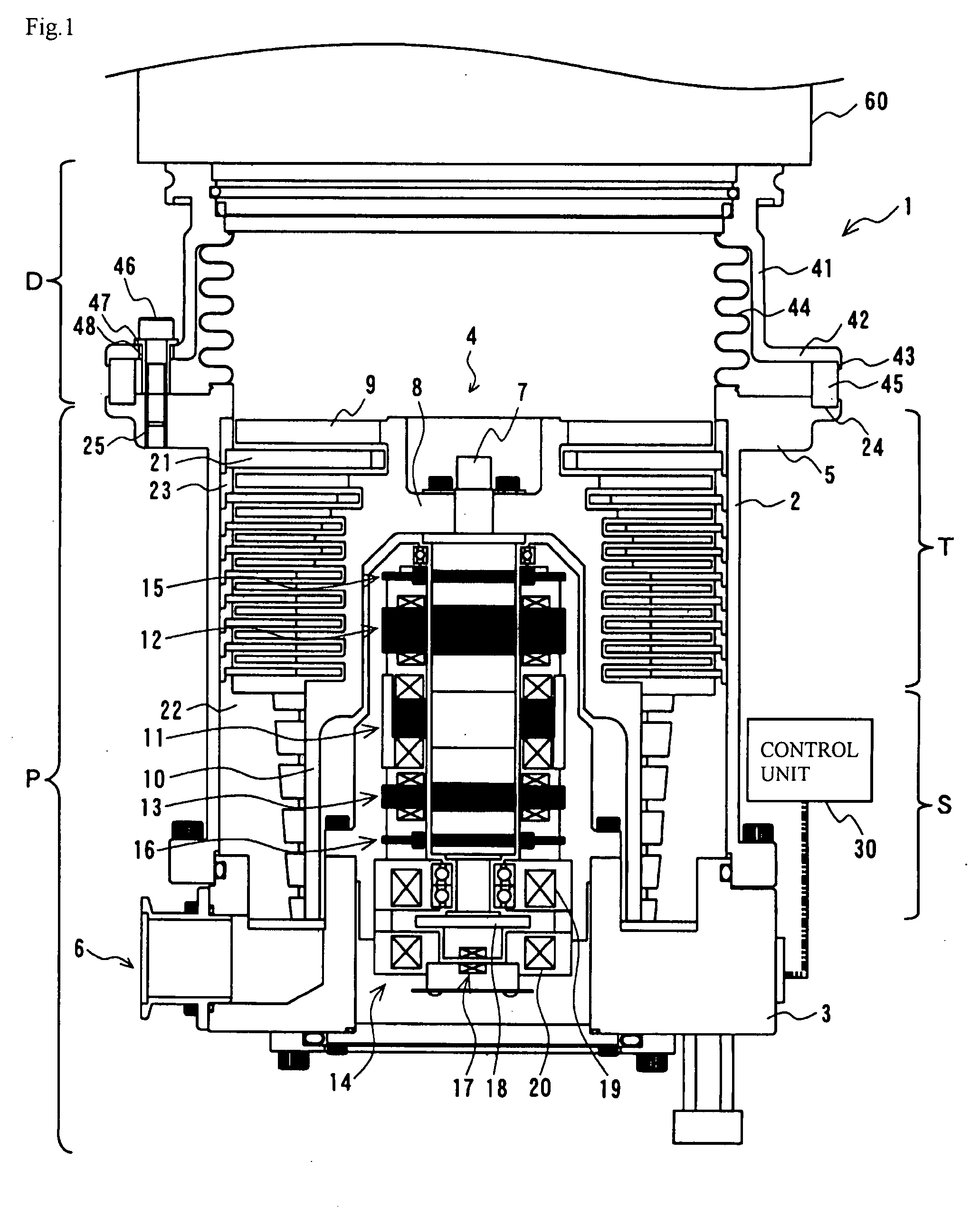
[0046] A preferred embodiment of the present invention will now be described in detail with reference to FIGS. 1 to 9. In this embodiment, explanation is given by using a turbo-molecular pump as one example of a vacuum pump.

[0047]FIG. 1 is a configuration view showing a construction of a turbo-molecular pump 1 provided with a damper section D in accordance with this embodiment. FIG. 1 shows a cross section in the axial direction.

[0048]FIG. 1 also shows a part of a vacuum system 60 connected to the turbo-molecular pump 1.

[0049] The turbo-molecular pump 1 in accordance with this embodiment consists of the damper section D and a pump section P. Further, the pump section P includes a turbo-molecular pump section T and a thread groove pump section S.

[0050] A casing 2 that forms an exterior body of the pump portion P of the turbo-molecular pump 1 has a substantially cylindrical shape, and forms a housing for the pump section P together with a base 3 provided under (on the exhaust port...


PUM


Abstract

To provide a damper capable of reducing vibrations in a particular frequency band while holding the degree of freedom of installation posture of a vacuum pump. A bellows 44 and an elastic member 45 are arranged with a clearance sufficient enough to prevent contact being provided. The elastic member 45 is provided with a spring element K and a damping element C, and the bellows 44 is provided with a spring element k and a mass element m. Thus, a notch filter type vibration isolator is formed. The bellows 44 and the elastic member 45 are set at constants of the elements such that the center frequency (fc) of a notch band is close to the rotation frequency of a rotor 8. The material and expansion amount of member are adjusted so as to agree with the constants of the elements. By the notch filter type vibration isolator formed by the bellows 44 and the elastic member 45 in this manner, the vibrations of a particular frequency, that is, the vibrations in the rotation frequency band of the rotor 8 can be damped suitably.

Description

BACKGROUND OF THE INVENTION [0001] 1. Field of the Invention [0002] The present invention relates to a damper having a mechanism for restraining the propagation (conduction) of vibrations produced in a vacuum pump. [0003] 2. Description of the Related Art [0004] As an apparatus using a vacuum stem such that the interior thereof is kept in a vacuum by accomplishing evacuation using a vacuum pump, semiconductor manufacturing equipment, an electron microscope, a surface analyzer, fine processing equipment, and the like can be cited. [0005] Also, of various types of vacuum pumps, a vacuum pump that is often used to realize a high-vacuum environment is a turbo-molecular pump. [0006] The turbo-molecular pump is configured so that a rotor rotates at a high speed in a casing having a suction port and an exhaust port. On the inner peripheral surface of the casing, stator blades are disposed in a multistage manner. On the other hand, on the rotor, rotor blades are disposed radially in a multi...

Claims


Application Information

Patent Timeline
Patent Type & Authority Applications(United States)
IPC IPC(8): F04B11/00
CPCF04D29/601F16F15/085F16F7/1028F04D29/668F04D19/04F04B37/14
Inventor NAMIKI, HIROTAKAOKUDERA, SATOSHI
Owner EDWARDS JAPAN
Why Eureka
Try Eureka