
Hot Runner System Sensor

Inactive Publication Date: 2008-04-10
HUSKY INJECTION MOLDING SYST LTD
View PDF47 Cites 29 Cited by
  • Summary
  • Abstract
  • Description
  • Claims
  • Application Information

AI Technical Summary

Benefits of technology

[0012]The sensing element may be secured to the internal surface of the cavity using chemical vapor deposition. Alternatively, the sensing element may be secured to the internal surface using physical vapor deposition, plasma spray, welding, brazing, or using an adhesive.
[0013]According to another embodiment, the present disclosure features a sensor for use with a hot runner system manifold. The sensor includes a plug sized and shaped to fit within a residual hole of the manifold and a substrate having a first surface adapted to be exposed to the resin in the passageway in the manifold and an internal surface that does not contact the resin. A sensing element is secured to the internal surface of the substrate. The plug may i

Problems solved by technology

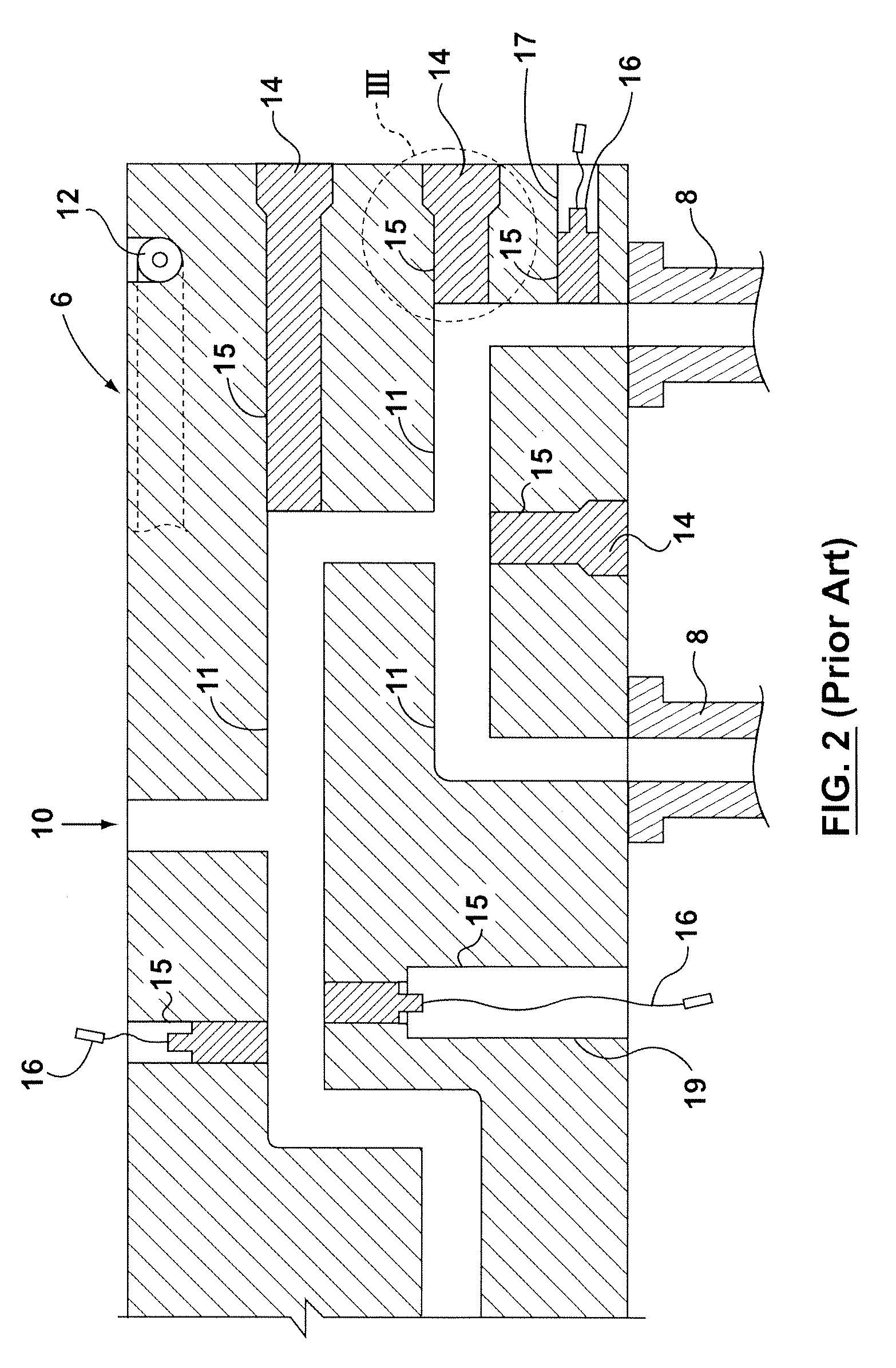
Unfortunately, the plugs 14 in the residuals holes 15 are prone to leakage.
The addition of these holes 17 increases labor costs, weakens the overall structural strength of the manifold 6, creates additional areas for resin leakage, and creates additional areas were resin may not flow and degrade.
However, if the force exerted by the ejector pin 112 is too large, the ejector pins 112 can damage the part 108.
Another limitation of this arrangement is that the pressure sensor 118 is difficult to fit between the bolt 119 and the end 117 of the ejector pin 112.
Furthermore, the wires 121 are often routed close to moving parts (e.g., the bolt 119) and may become damaged if they come into contact with a moving part.
Yet a further limitation of this arrangement is that the pressure sensor 118 wears out quickly.

Method used


Image

  • Hot Runner System Sensor
  • Hot Runner System Sensor
  • Hot Runner System Sensor

Examples


Embodiment Construction

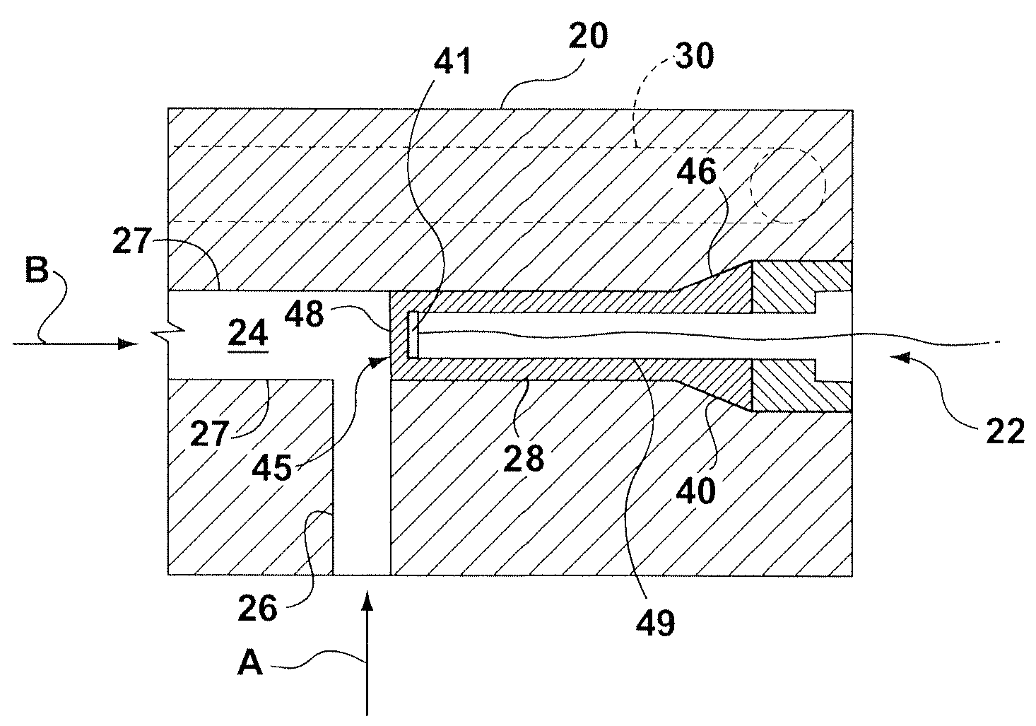
[0025]According to one embodiment, an improved manifold 20 and manifold sensor 22, FIGS. 4 and 5, may be used with a hot runner system as described above. The manifold 20 may include a passageway 24 that distributes resin to the various nozzles (not shown) which are connected to the manifold 20 and may also includes a heating device 30 (typically an electrical resistance wire or the like) in close proximity to the passageway 24. Because of the different positions of the nozzles along the manifold 20, the passageway 24 is generally not straight and typically includes segments 26, 27 at different heights, levels and / or angles. Only a small, representative portion of a typical manifold 20 and passageway 24 is shown for illustrative purposes only. Those skilled in the art will recognize that the shape, size, and configuration of the manifold 20 and the passageway 24 according to the present disclosure will depend upon the intended application.

[0026]The segments 26, 27 of the passageway ...


PUM


Abstract

A plug for use with a residual hole of a passageway in a hot runner system manifold may include an external surface for sealing with the residual hole, wherein a portion of the external surface is in direct contact with the resin in the passageway, a cavity having an internal surface that does not contact the resin, and a sensor secured to the internal surface using chemical vapor deposition, physical vapor deposition, plasma spray, or an adhesive. An ejector pin may include a sensor secured to the sidewall using chemical vapor deposition, physical vapor deposition, plasma spray, or an adhesive. A mold may include two inserts each an external surface and an internal surface defining a mold cavity. A sensing element may be secured to the external surface the first or second mold inserts wherein the sensing element does not contact the internal surface of the mold cavity.

Description

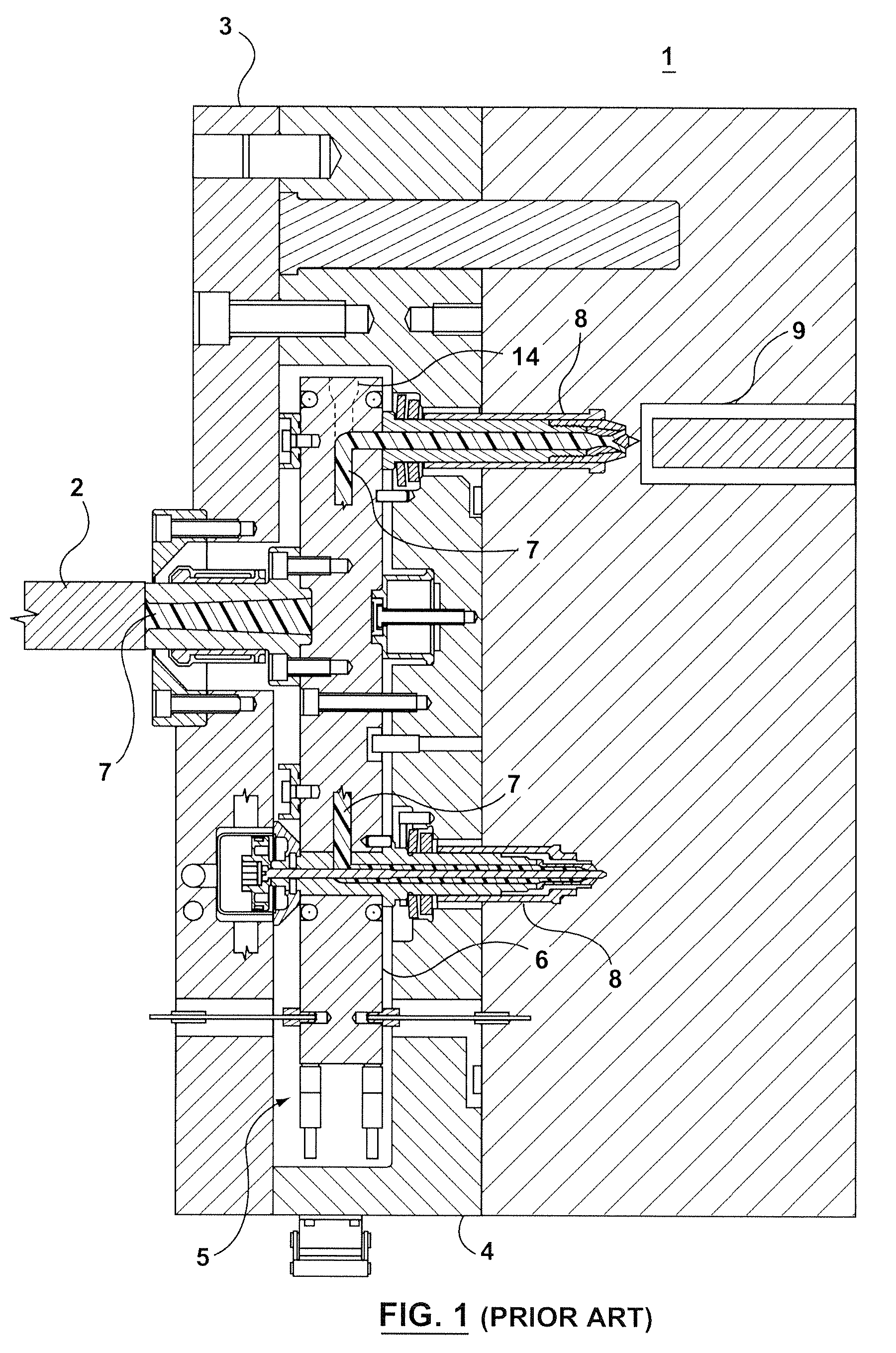
TECHNICAL FIELD[0001]The present disclosure relates to molding systems and more particularly, relates to sensors for use in injection molding systems.BACKGROUND INFORMATION[0002]Hot runner systems 1, FIG. 1, are well known in the art. A typical hot runner system 1 generally transfers molten plastic or metal (hereinafter “resin”) from a machine injection unit 2 to a mold 9 through a series of heated melt channels 7. A hot runner backing plate 3 and a manifold plate 4 are typically secured to a stationary platen on the injection molding machine and define a cavity 5 sized and shaped to accept a manifold 6. In practice, the machine injection unit 2 forces resin under high temperature and pressure through the melt channels 7 of the manifold 6 which distributes the resin to one or more nozzles 8 (typically either a valve gated or thermally gated nozzle) wherein the resin fills the mold 9 as is well known in the prior art.[0003]Referring specifically to FIG. 2, a cross-section of the mani...

Claims


Application Information

Patent Timeline
IPC IPC(8): B28B17/00
CPCB29C2945/7604B29C2945/7628B29C45/2738B29C2945/76006B29C45/78B29C2045/2722B29C2045/274B29C45/77
Inventor BARNETT, DANIEL WAYNE
Owner HUSKY INJECTION MOLDING SYST LTD
Learn More