
Blast mitigation system

Inactive Publication Date: 2008-04-17
EMEK MORDECHAY
View PDF12 Cites 19 Cited by
  • Summary
  • Abstract
  • Description
  • Claims
  • Application Information

AI Technical Summary

Benefits of technology

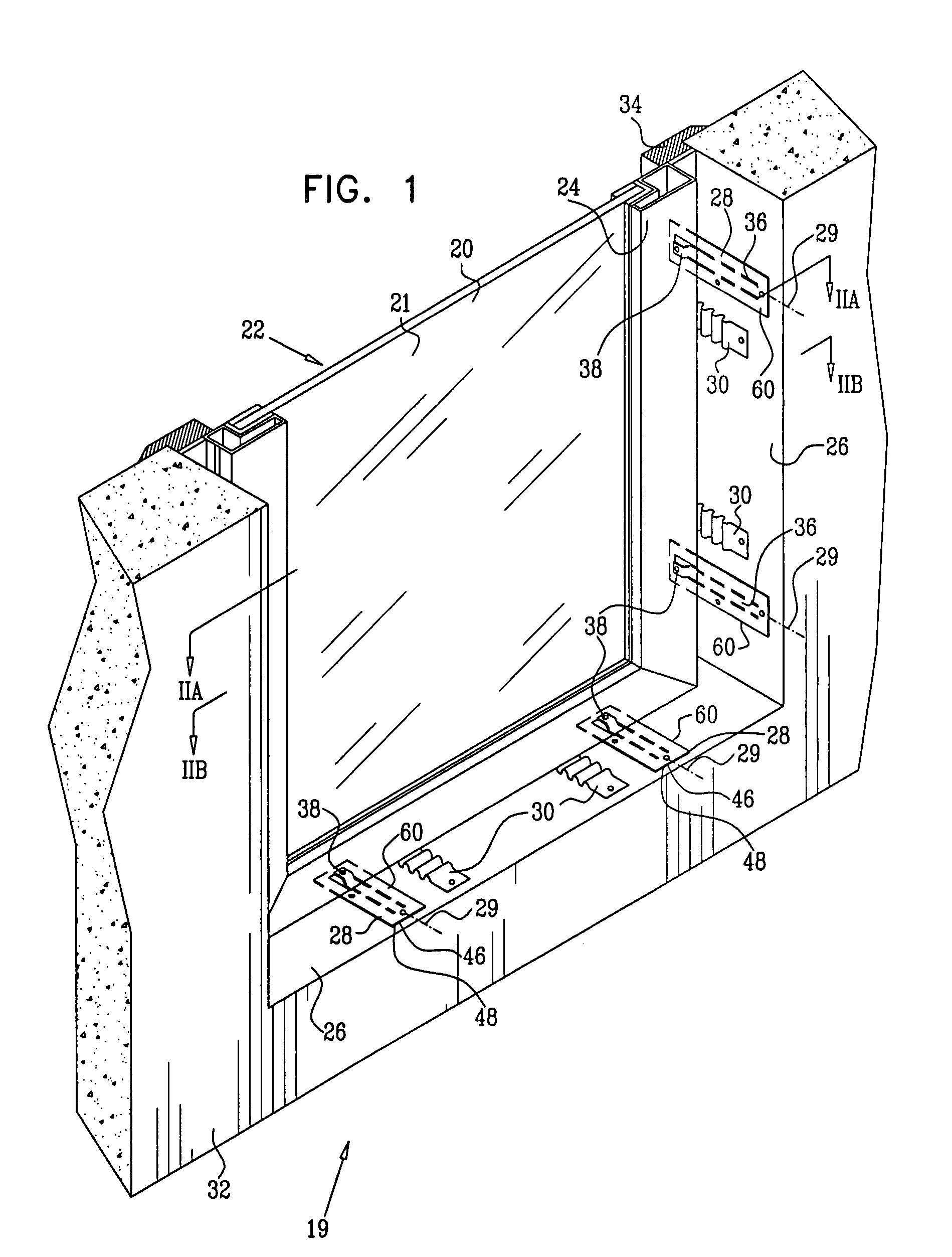
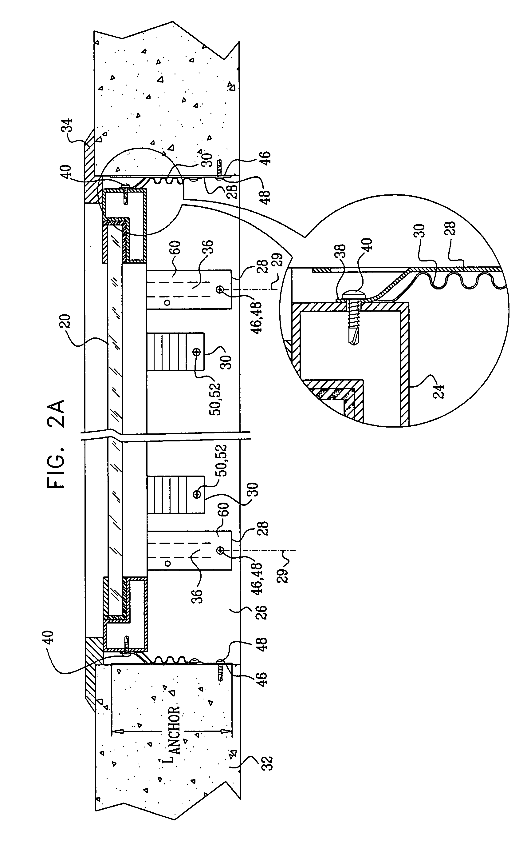
[0007] In embodiments of the present invention, a window anchor is formed with a tongue fixed to, and typically partially protruding from, a base plate. The tongue is connected to the base plate at one or more regions which are designed to shear in a particular direction, termed the axis of the anchor, so that the tongue may shear away from the base plate. The regions are hereinbelow termed shear-regions. A multiplicity of anchors are attached to an opening for a window, and the tongue of each anchor is attached to a frame of the window, thereby mounting and retaining the window and its frame in the opening. The axes of the anchors are aligned so that on receipt of a blast, the tongues shear from their base plates. During the shearing, the tongues remain attached to both the frame and their base plates, so that the window moves as a whole. The shearing of the shear-regions absorbs much of the blast energy, and this energy absorption, together with the ability of the window to move as a whole, substantially mitigates blast effects on the window.
[0008] In some embodiments, the shear-regions are divided into different sub-regions, each having a respective force level before activating, i.e., shearing, and a respective length. The sub-regions activate sequentially. In one embodiment there are three sub-regions, a first and a third sub-region having a high force of activation. In a second sub-region, intermediate the first and third sub-regions, the base plate is weakened so as to have a lower force of activation compared to the other sub-regions. The first sub-region has a short length, while the other regions are longer, although the lengths and forces of activation of the sub-regions may be adjusted to accord with window requirements. The high force of activation of the first sub-region means that the window is held in place firmly in the case of non-blast situations, such as high wind, while the short length of the sub-region ensures that once activated there is very little time before the second sub-region activates. Typically the anchor is manufactured by a stamping process in a press, so that parameters of the different sub-regions may be easily adjusted for different window requirements by altering the press.

Problems solved by technology

Openings in the wall reduce the protection provided, and if the opening comprises a glazed window, the blast typically shatters the glass.
The shattering of the glass may harm the occupants.
While this approach may provide the desired level of protection to the occupants, it typically requires a substantial thickness of laminated glass and relatively heavy framing.
Furthermore, the anchorage required to accommodate the substantial reaction forces presents major construction challenges.

Method used


Image

  • Blast mitigation system
  • Blast mitigation system
  • Blast mitigation system

Examples


Embodiment Construction

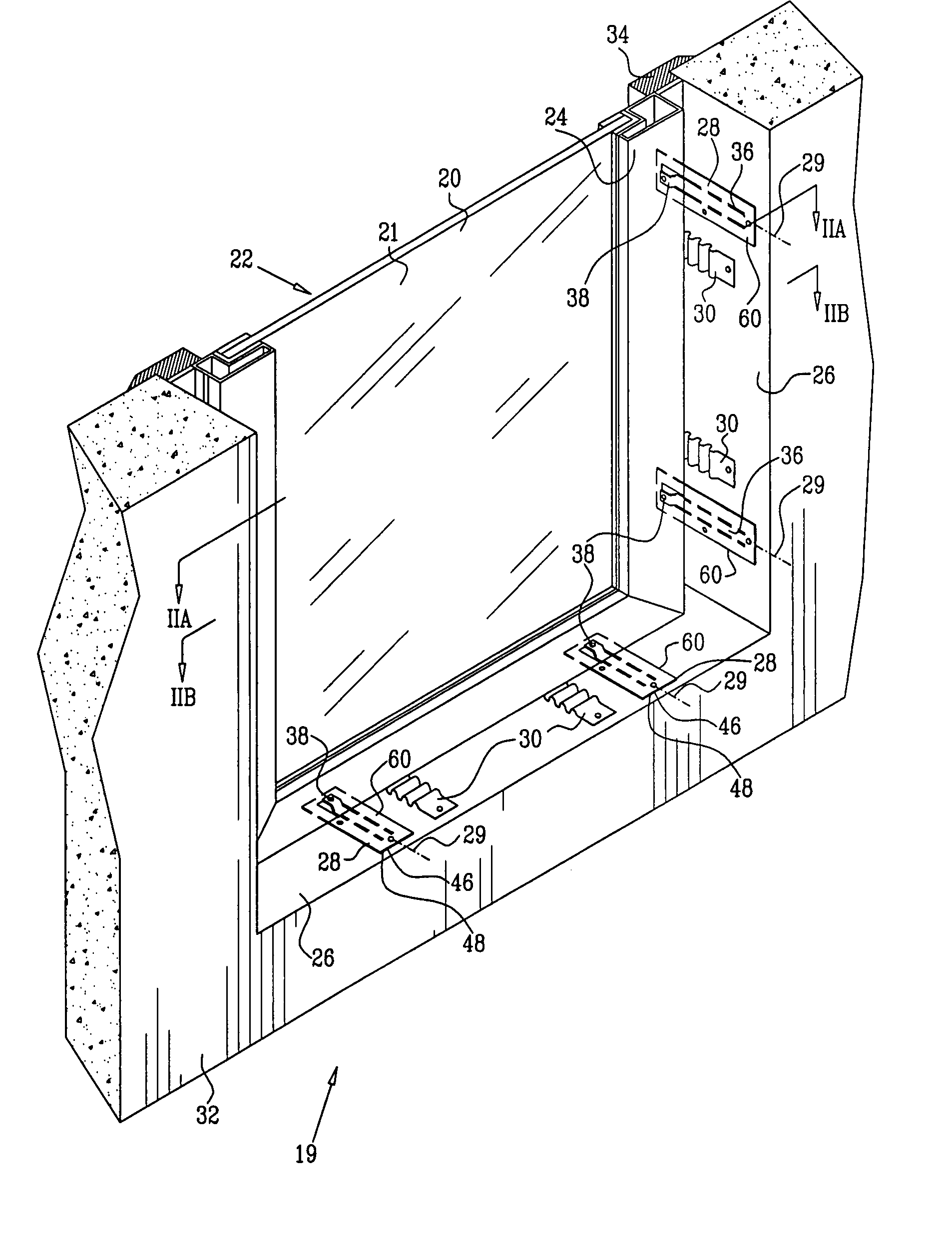
[0042] Reference is now made to FIG. 1, which is a schematic isometric drawing of a window mounting assembly 19, according to an embodiment of the present invention. Reference is also made to FIGS. 2A and 2B, which are cross-sections of FIG. 1. FIGS. 1, 2A, and 2B, show a window 20 mounted in an opening 22 of a structure 32. In the specification and in the claims, the term window is also assumed to comprise a door, curtain-wall, and / or other fenestration product which may be mounted in an opening of a structure. Window 20 comprises a retaining frame 24, typically formed from extruded aluminum, and for clarity a top portion of frame 24 is not shown in the figure. Window 20 has internal material 21, typically glazing, although it will be appreciated that the internal material may be formed from other materials suitable for mounting within frame 24, such as plastic or metal sheet. Internal material 21 is typically laminated, or has another form of protection known in the art, so that i...


PUM


Abstract

A blast-resistant window assembly (19), including a window opening (22), and a window (20) sized to fit within the window opening. The assembly further includes at least one anchor (28), which consists of a base plate (60) connected to the window opening. The anchors have a tongue (36), which is connected to the window and is fixed to the base plate at a shear region (61) that is configured so that under force of a blast against the window, the tongue shears away from the base plate, thereby absorbing energy of the blast.

Description

FIELD OF THE INVENTION [0001] The present invention relates generally to reducing the effects of blast, and specifically to reducing the effects of blast on windows within a structure. BACKGROUND OF THE INVENTION [0002] The wall of an enclosed structure provides a measure of protection to occupants of the structure if a blast occurs outside the structure. Openings in the wall reduce the protection provided, and if the opening comprises a glazed window, the blast typically shatters the glass. [0003] The shattering of the glass may harm the occupants. [0004] Methods for mitigating the effects of blast on windows are known in the art. Conventional hardened window systems rely on the capacity of the glazing, which is retained within robust frames. Not only must the relatively stiff framing withstand the large forces collected by the glazing, but the structure to which these windows are attached must be able to accept the reaction forces. While this approach may provide the desired level...

Claims


Application Information

Patent Timeline
IPC IPC(8): E06B5/10E04G17/00E06B9/56
CPCE06B9/02E06B5/12E04H9/14E06B7/00
Inventor EMEK, MORDECHAY
Owner EMEK MORDECHAY
Learn More