
Motor Vehicle Pneumatic Tyre

a technology for pneumatic tires and motor vehicles, applied in the field of vehicle pneumatic tires, can solve problems such as difficulties in irregularities, and achieve the effect of improving the effect of covering slight irregularities

Inactive Publication Date: 2008-04-17
CONTINENTAL AG
View PDF6 Cites 21 Cited by
  • Summary
  • Abstract
  • Description
  • Claims
  • Application Information

AI Technical Summary

Benefits of technology

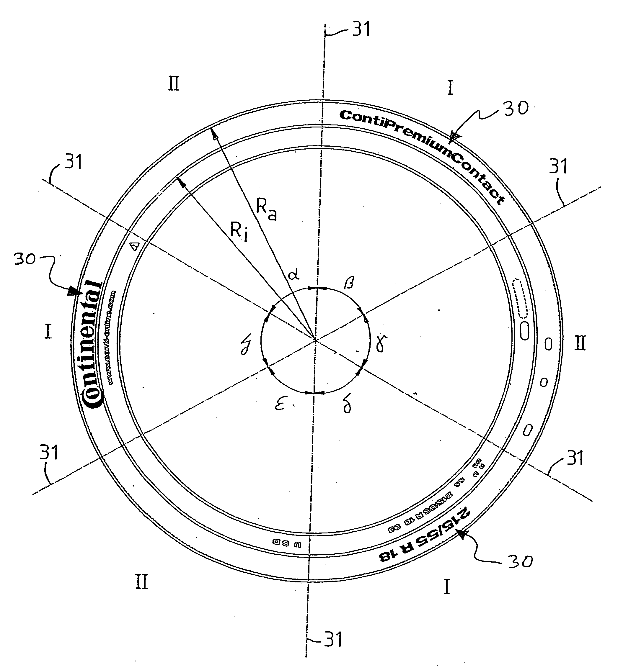
[0010]The invention improves the effect of covering slight irregularities in the outer contour of the vehicle tire sidewall.
[0012]An embodiment is particularly advantageous when the first family of curves is made up of undulatory curves that extend in the circumferential direction of the vehicle pneumatic tire. This renders possible in a simple manner a transition occurring in the circumferential direction of the families of curves of individual circumferential sections and a repeat.
[0013]An embodiment is particularly advantageous when the second family of curves is made up of undulatory curves with irregular wave form which extend in the circumferential direction of the vehicle pneumatic tire. This renders possible in a simple manner a transition occurring in the circumferential direction of the families of curves of individual circumferential sections and a repeat.
[0014]Due to the simple targeted irregularity, an embodiment according can be particularly advantageous when the second family of curves is made up of undulatory curves with irregular frequency of their wave form. Irregularities can be hidden particularly well in, behind or under other irregularities.
[0015]Due to the simple targeted irregularity, an embodiment according can be particularly advantageous when the second family of curves is made up of undulatory curves with varied amplitude along their wave propagation, whereby the second family of curves is made up of undulatory curves with irregular frequency of their wave form. Irregularities can be hidden particularly well in, behind or under other irregularities.

Problems solved by technology

This makes it particularly difficult for irregularities, e.g., caused by constriction effects of the sidewall, in the tire sidewall contour to be detected by the human eye.

Method used


Image

  • Motor Vehicle Pneumatic Tyre
  • Motor Vehicle Pneumatic Tyre
  • Motor Vehicle Pneumatic Tyre

Examples


Embodiment Construction

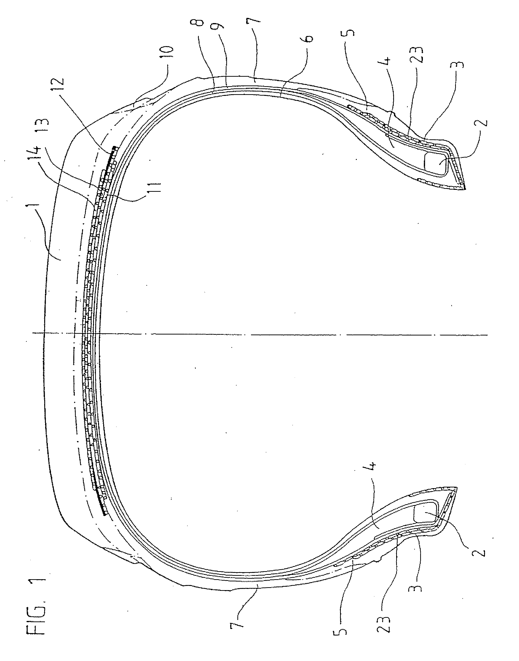
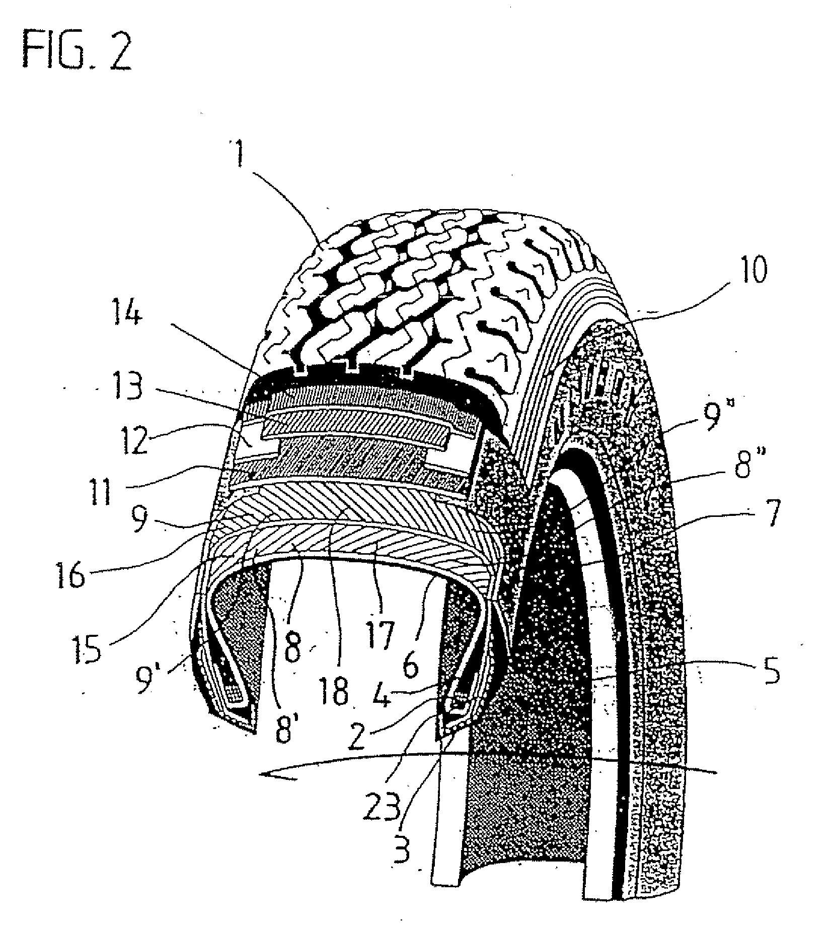
[0030]FIGS. 1 and 2 diagrammatically illustrate the structure of a vehicle pneumatic tire, by way of example, in which, around a core 2 with a core profile 4, a first carcass ply 8 extends beyond a dense inner layer 6 over the right shoulder region and the zenith plane to the left shoulder region and the left core 2 with core profile 4, around which it is laid in a conventional manner. A second carcass ply 9, which likewise extends from the side of the tire shown on the right in FIG. 1 to the side shown on the left, is laid in a conventional manner over the first carcass ply 8. Both carcass plies are manufactured in a conventional manner from a carcass ply / rubber mixture of known type, and with rubber bands built up with textile yarns 8 or 9 of known construction embedded therein and lying respectively parallel to one another.

[0031]These rubber bands are cut on the bias on a cutting table in a known manner and are then joined to one another at their parallel uncut sides.

[0032]For ea...


PUM


Abstract

Vehicle pneumatic tire includes a carcass having sidewalls and a tread rubber. A sidewall area is covered on an outside by a sidewall rubber strip. A moiré pattern is arranged on the sidewall rubber strip and is formed by a superimposition of at least two linear non-identical families of curves. A first family of curves of the at least two linear non-identical families of curves is formed by undulatory curves having regular wave form. A second family of curves of the at least two linear non-identical families of curves is formed by undulatory curves having irregular wave form. This abstract is not intended to define the invention disclosed in the specification, nor intended to limit the scope of the invention in any way.

Description

CROSS-REFERENCE TO RELATED APPLICATIONS[0001]The present application is a U.S. National Stage of International Patent Application No. PCT / EP2005 / 007384 filed Jul. 8, 2005 which published as WO 2006 / 015674 on Feb. 16, 2006, and claims priority of German Patent Application No. 10 2004 038 141.0 filed Aug. 6, 2004.BACKGROUND OF THE INVENTION[0002]1. Field of the Invention[0003]The invention relates to a vehicle pneumatic tire with a carcass, in particular, utilizing a radial construction, sidewalls and a tread rubber. The carcass is outwardly covered with a sidewall rubber strip in the sidewall area.[0004]2. Discussion of Background Information[0005]Constructing vehicle pneumatic tires from several different layers from the radial inside to the radial outside is known, e.g., with tires of radial construction having an inner layer, carcass, belt and tread rubber, and in the side region having an inner layer, carcass and side area. Carcasses of vehicle pneumatic tires are usually constru...

Claims


Application Information

Patent Timeline
IPC IPC(8): B60C13/02B60C13/00
CPCB60C13/001
Inventor METZ, MARKUS
Owner CONTINENTAL AG
Learn More