Method of load shedding to reduce the total power consumption of a load control system

load shedding technology, applied in the field of load shedding to reduce the total power consumption of a load control system, can solve the problems of increasing the total power cost of the electric consumer, increasing the cost of power meters, and increasing the cost of lighting controllers including current transformers. , to achieve the effect of reducing the value of the setpoint, and reducing the amount of power

Inactive Publication Date: 2008-04-17
LUTRON TECH CO LLC
View PDF45 Cites 117 Cited by
  • Summary
  • Abstract
  • Description
  • Claims
  • Application Information

AI Technical Summary

Benefits of technology

[0018]According to another aspect of the present invention, a method of determining a setpoint of a load control device for controlling the amount of power delivered to an electrical load located in a space comprises the steps of: (1) initially setting the value of the setpoint equal to a desired level; (2) limiting the value of the setpoint to an occupied high-end trim if the space is occupied; (3) limiting the value of the setpoint to a daylighting high-end trim determined by a daylighting procedure; and (4) subsequently reducing the value of the setpoint in response to a load shed parameter.
[0019]According to another embodiment of the present invention, a method of controlling the amount of power delivered from an AC power source to an electrical load located in a space, comprises the steps of: (1) receiving a digital message containing a command to control the amount of power delivered to the electrical load to a desired level; (2) detecting if the space is occupied; and (3) determining a daylighting high-end trim using a daylighting procedure. The improvement comprises the steps of: (4) receiving a load shed parameter; and (5) determining the amount of power to be delivered to the electrical load by limiting the amount of power to be delivered to the electrical load to the minimum of the desired level of the digital message, an occupied high-end trim, and the daylighting high-end trim, and by reducing the amount of power to be delivered to the electrical load in response to the load shed parameter.
[0020]The present invention further provides a load control device for controlling the amount of power delivered from an AC power source to an electrical load located in a space. The load control device comprises: (1) means for initially setting the value of the setpoint equal to a desired level; (2) means for limiting the value of the setpoint to an occupied high-end trim if the space is occupied; (3) means for limiting the value of the setpoint to a daylighting high-end trim determined by a daylighting procedure; and (4) means for subsequently reducing the value of the setpoint in response to a load shed parameter.
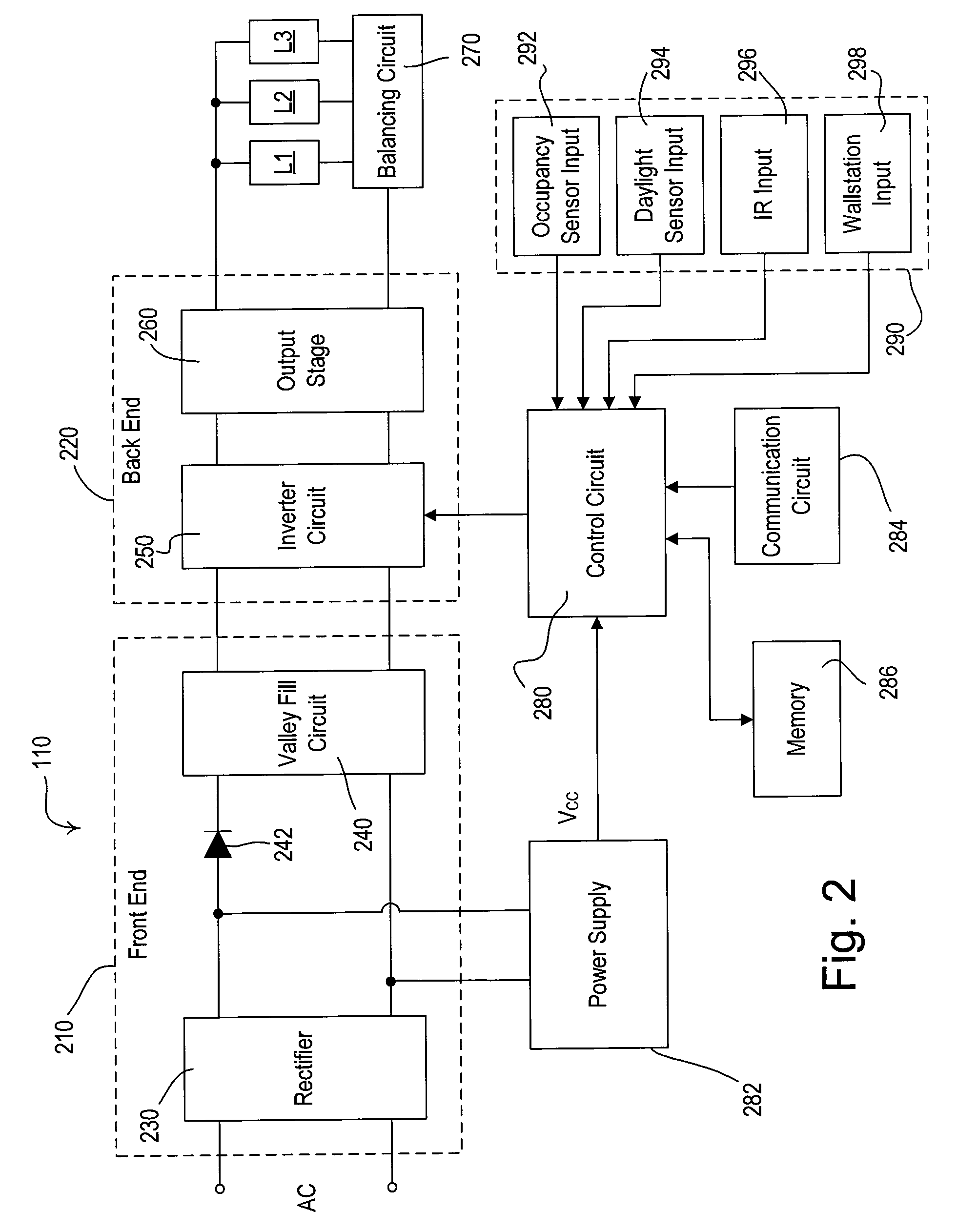
[0021]In addition, the present invention provides a load control device of a load control system for controlling the amount of power delivered from an AC power source to an electrical load located in a space. The load control device comprises a load control circuit, a control circuit, a memory, a communication circuit, an occupancy sensor input, and a daylight sensor input. The load control circuit is adapted to be coupled to the AC power source and the electrical load to control the amount of power delivered to the electrical load. The control circuit is coupled to the load control circuit for controlling the amount of power delivered to the electrical load, to the memory for storing a load shed parameter, and to the communication circuit for receiving a digital message representative of a desired amount of power to deliver to the electrical load. The occupancy sensor input receives an occupancy sensor signal representative of whether the space is occupied, such that the control circuit is operable to determine an occupied high-end trim in response to the occupancy sensor signal. The daylight sensor input receives a daylight sensor signal representative of the total illumination in the space, such that the control circuit is operable to determine a daylighting high-end trim in response to the daylighting sensor signal. The control circuit is operable to determine the amount of power to be delivered to the electrical load by limiting the amount of power to be delivered to the electrical load to the minimum of the desired level of the digital message, the occupied high-end trim, and the daylighting high-end trim, and by reducing the amount of power to be delivered to the electrical load in response to the load shed parameter.

Problems solved by technology

Thus, even if an electricity consumer consumes power at a very high rate for only a short period of time, the electricity consumer will face a significant increase in its total power costs.
Since power meters tend to be rather expensive, most prior art electrical systems have included only one power meter monitoring the total power being consumed by the electrical system.
However, lighting controllers including current transformers are also expensive.

Method used


Image

  • Method of load shedding to reduce the total power consumption of a load control system
  • Method of load shedding to reduce the total power consumption of a load control system
  • Method of load shedding to reduce the total power consumption of a load control system

Examples


Embodiment Construction

[0029]The foregoing summary, as well as the following detailed description of the preferred embodiments, is better understood when read in conjunction with the appended drawings. For the purposes of illustrating the invention, there is shown in the drawings an embodiment that is presently preferred, in which like numerals represent similar parts throughout the several views of the drawings, it being understood, however, that the invention is not limited to the specific methods and instrumentalities disclosed.

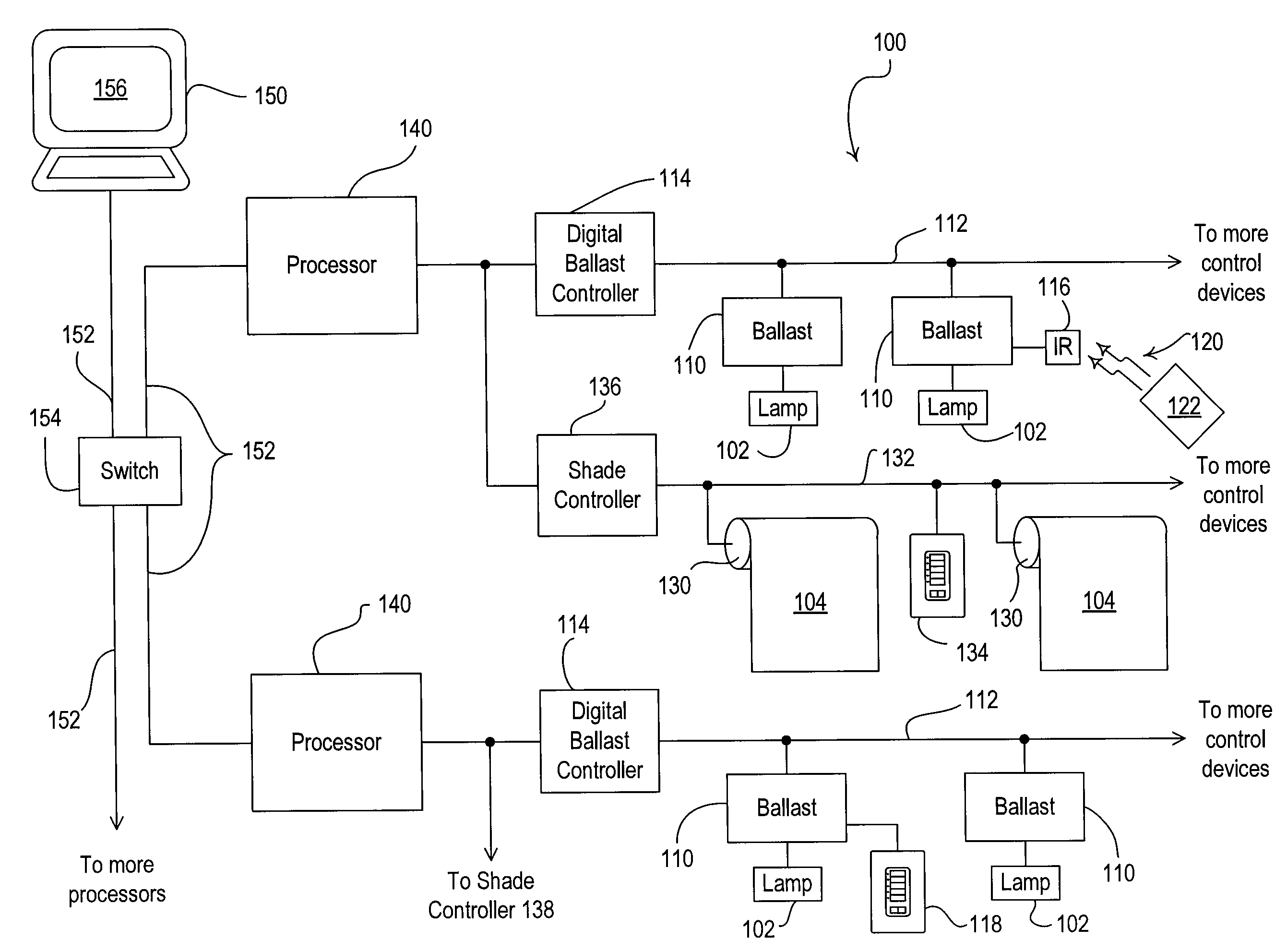
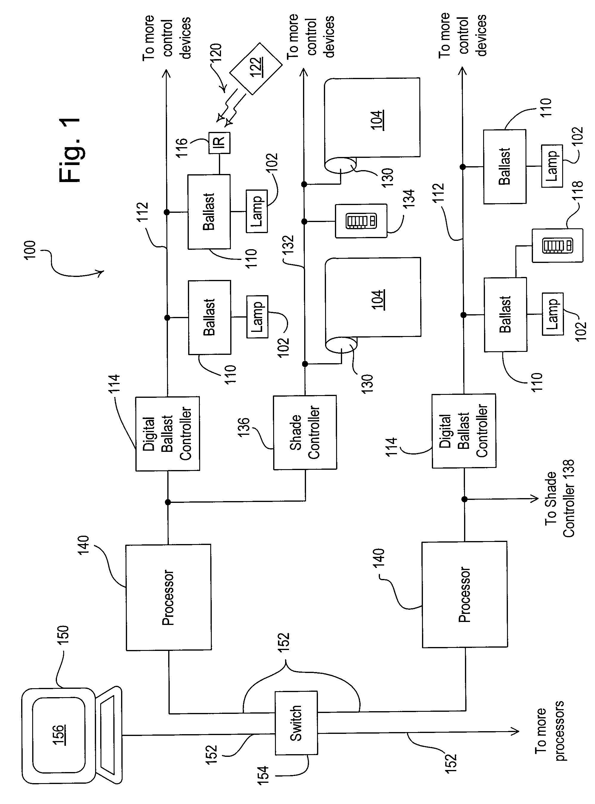
[0030]FIG. 1 is a simplified block diagram of a lighting control system 100 according to the present invention. Preferably, the lighting control system 100 is operable to control the level of illumination in a space by controlling the intensity level of the electrical lights in the space and the daylight entering the space. As shown in FIG. 1, the lighting control system 100 is operable to control the amount of power delivered to (and thus the intensity of) a plurality of lighti...


PUM


Abstract

A lighting control system is operable to control the amount of power delivered to a plurality of electrical loads. The lighting control system includes load control devices (such as digital electronic dimming ballasts), motorized window treatments, controllers, processors, and personal computers. The personal computer is preferably executing a graphical user interface (GUI) software, which allows a user to configure and monitor the operation of the lighting control system. The lighting control system offers a load shedding functionality without using power meters. Each load control device transmits its current intensity level to the personal computer, which is operable to determine a total power consumption of the lighting control system. If the total power consumption exceeds a predetermined power threshold, the personal computer causes the load control devices to shed loads.

Description

RELATED APPLICATIONS[0001]This application claims priority from commonly-assigned U.S. Provisional Application Ser. No. 60 / 851,383, filed Oct. 13, 2006, and U.S. Provisional Application Ser. No. 60 / 858,844, filed Nov. 14, 2006, both entitled LIGHTING CONTROL SYSTEM. The entire disclosures of both applications are hereby incorporated by reference.BACKGROUND OF THE INVENTION[0002]1. Field of the Invention[0003]The present invention relates to a load control system comprising a plurality of load control devices for controlling the amount of power delivered to a plurality of electrical loads from an AC power source, and more particularly, to a method of shedding loads of a lighting control system in response to an estimation of the amount of power presently being consumed by the lighting control system.[0004]2. Description of the Related Art[0005]Reducing the total cost of electrical energy is an important goal for many electricity consumers. Most electricity customers are charged for t...

Claims


Application Information

Patent Timeline
Patent Type & Authority Applications(United States)
IPC IPC(8): H02J3/12
CPCH02J3/14Y04S20/222Y02B70/3225H05B41/3921Y04S20/246Y02B70/30H02J2310/60
Inventor CASH, AUDWIN W.HOWE, WILLIAM H.JACOB, JOE SURESHMAJEWSKI, TIMOTHY S.RIGATTI, CHRISTOPHER J.VESKOVIC, DRAGAN
Owner LUTRON TECH CO LLC
Why Eureka
Try Eureka