Poly-phasic multi-coil generator

a generator and polyphasic technology, applied in the field of generators, can solve the problems of reducing the efficiency of the generator, narrowing the “efficient” operational range, and the system not creating an efficient generator, so as to reduce the negative impact of system faults, reduce system damage, and reduce the effect of system damag

a generator and polyphasic technology, applied in the field of generators, can solve the problems of reducing the efficiency of the generator, narrowing the “efficient” operational range, and the system not creating an efficient generator, so as to reduce the negative impact of system faults, reduce system damage, and reduce the effect of system damag

US20080088200A1Inactive Publication Date: 2008-04-17RITCHEY JONATHAN

Image

  • Poly-phasic multi-coil generator
  • Poly-phasic multi-coil generator
  • Poly-phasic multi-coil generator

Examples


Embodiment Construction

[0092] The following description is demonstrative in nature and is not intended to limit the scope of the invention or its application of uses.

[0093] There are a number of significant design features and improvements incorporated within the invention.

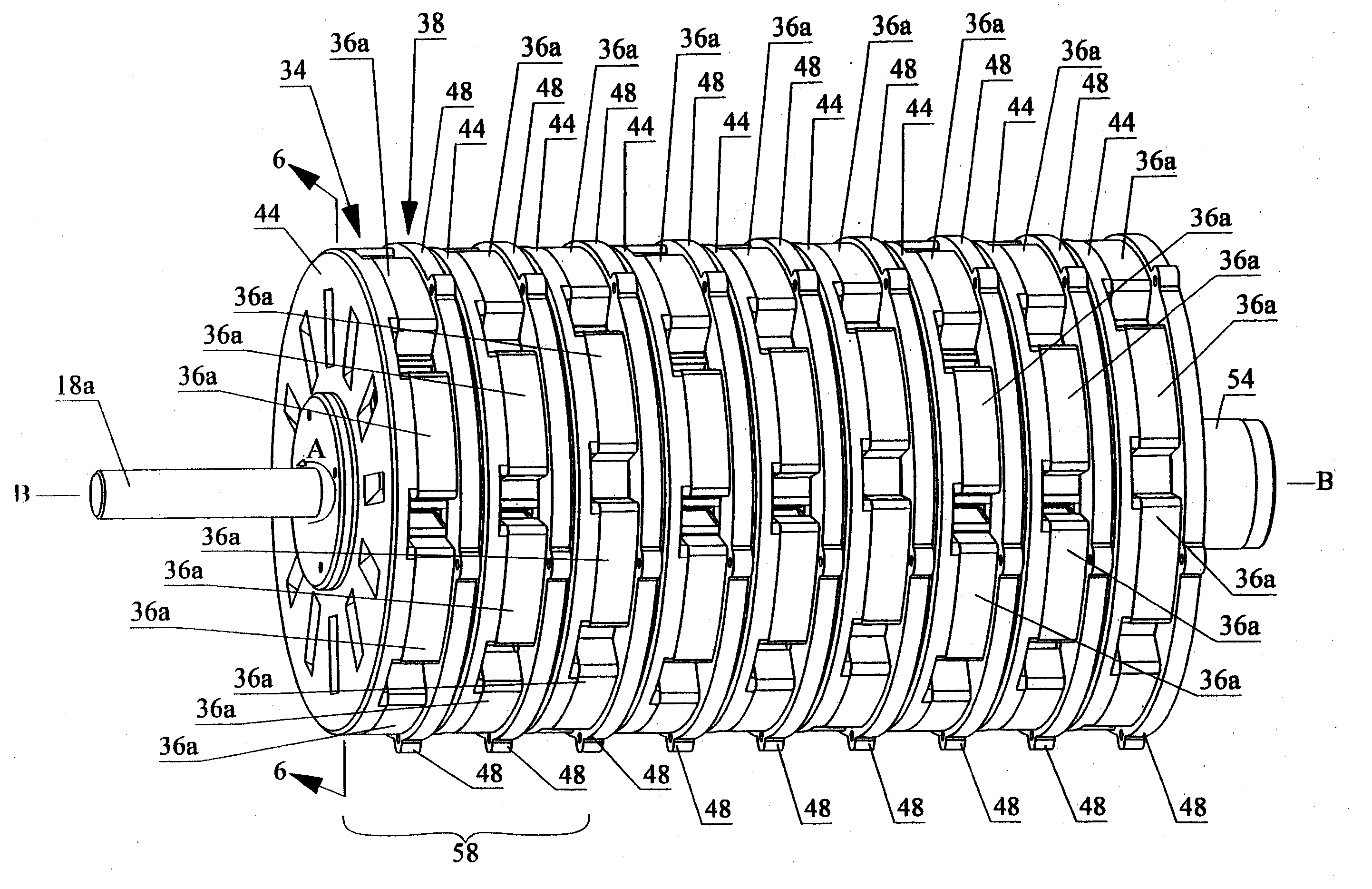
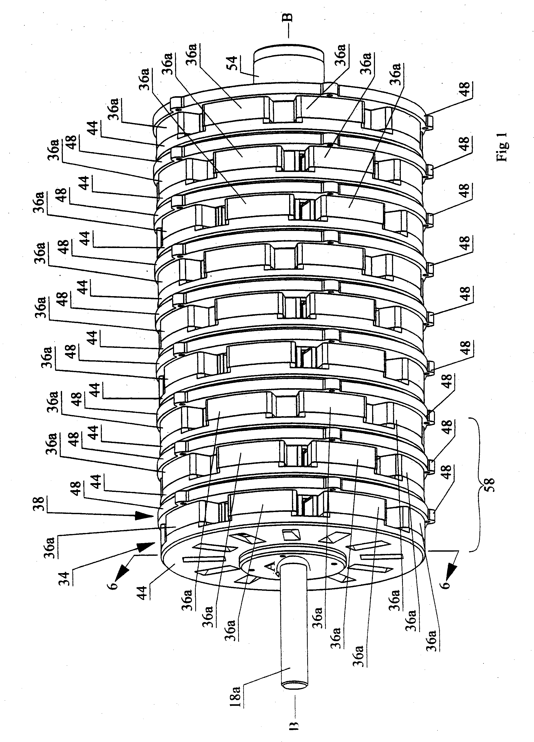
[0094] The device is a generator polyphasic multiple coils in staged staggered arrays.

[0095] Incorporated herein by reference in its entirety my U.S. Provisional Patent Application No. 60 / 600,723 filed Aug. 12, 2004 entitled Polyphasic Stationary Multi-Coil Generator. Where any inconsistency exists between these documents and this specification, for example in the definition of terms, this specification is to govern.

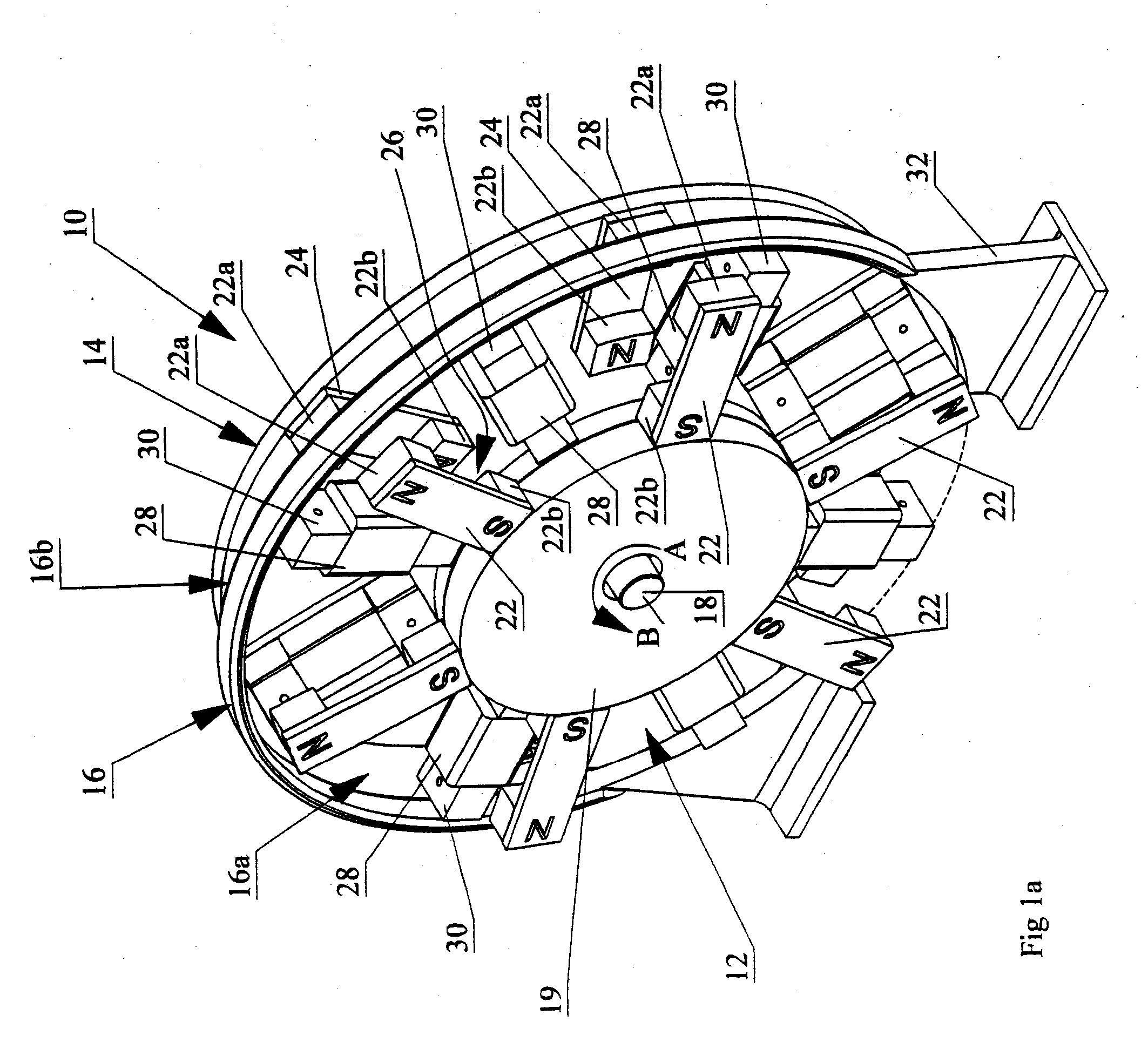
[0096] In FIG. 1a, wherein like reference numerals denote corresponding parts in each view, a single stage 10 of the polyphasic multi-coil generator according to the present invention includes a pair of rotors 12 and 14 lying in parallel planes and sandwiching there between so as to be interleaved in a plane parallel and...


PUM


Abstract

A polyphasic multi-coil generator includes a driveshaft, at least first and second rotors rigidly mounted on the driveshaft so as to simultaneously synchronously rotate with rotation of the driveshaft, and at least one stator sandwiched between the first and second rotors. The stator has an aperture through which the driveshaft is rotatably journalled. A stator array on the stator has an equally radially spaced-apart array of electrically conductive coils mounted to the stator in a first angular orientation about the driveshaft. The stator array is radially spaced apart about the driveshaft. The rotors and the stator lie in substantially parallel planes. The first and second rotors have, respectively, first and second rotor arrays.

Description

RELATED APPLICATIONS [0001] This application claims the priority date of U.S. Provisional Application No. 60 / 804,279 with a filing date of Jun. 8, 2006.BACKGROUND OF INVENTION [0002] 1. Field of the Invention [0003] The present invention relates to the field of generators, and more particularly, it relates to a generator having polyphasic multiple coils in staged staggered arrays. [0004] 2. Background of the Invention [0005] Conventional electric motors employ magnetic forces to produce either rotational or linear motion. Electric motors operate on the principle that when a conductor, which carries a current, is located in the magnetic field, a magnetic force is exerted upon the conductor resulting in movement. Conventional generators operate through the movement of magnetic fields thereby producing a current in a conductor situated within the magnetic fields. As a result of the relationship between conventional motors and generators, conventional generator technologies have focused...

Claims


Application Information

Patent Timeline
17 Apr 2008
Publication
US20080088200A1
IPC
H02K47/00; H02K21/12; H02K1/22
CPC
H02K16/00; H02K21/12; H02P9/48; H02P9/02; H02K3/28; H02K21/24; H02K19/16
Inventors
RITCHEY, JONATHAN