Method for forming an electrical interconnect to a spring layer in an integrated lead suspension

a technology of integrated suspension and spring layer, which is applied in the direction of integrated arm assemblies, maintaining head carrier alignment, instruments, etc., can solve the problems of increased cost, reduced reliability, and reduced process complexity

Inactive Publication Date: 2008-04-17
HUTCHINSON TECH
View PDF13 Cites 32 Cited by
  • Summary
  • Abstract
  • Description
  • Claims
  • Application Information

AI Technical Summary

Problems solved by technology

Either method can result in increased cost, process complexity, and decreased reliability.
The conductive adhesive has a higher resistance than is desirable and is prone to contamination.
Use of a plated ground feature adds process steps and cost to the integrated lead suspension.
Neither of these methods results in a ground feature that is flush with both the stainless steel and conductive layer surfaces.

Method used


Image

  • Method for forming an electrical interconnect to a spring layer in an integrated lead suspension
  • Method for forming an electrical interconnect to a spring layer in an integrated lead suspension
  • Method for forming an electrical interconnect to a spring layer in an integrated lead suspension

Examples


Embodiment Construction

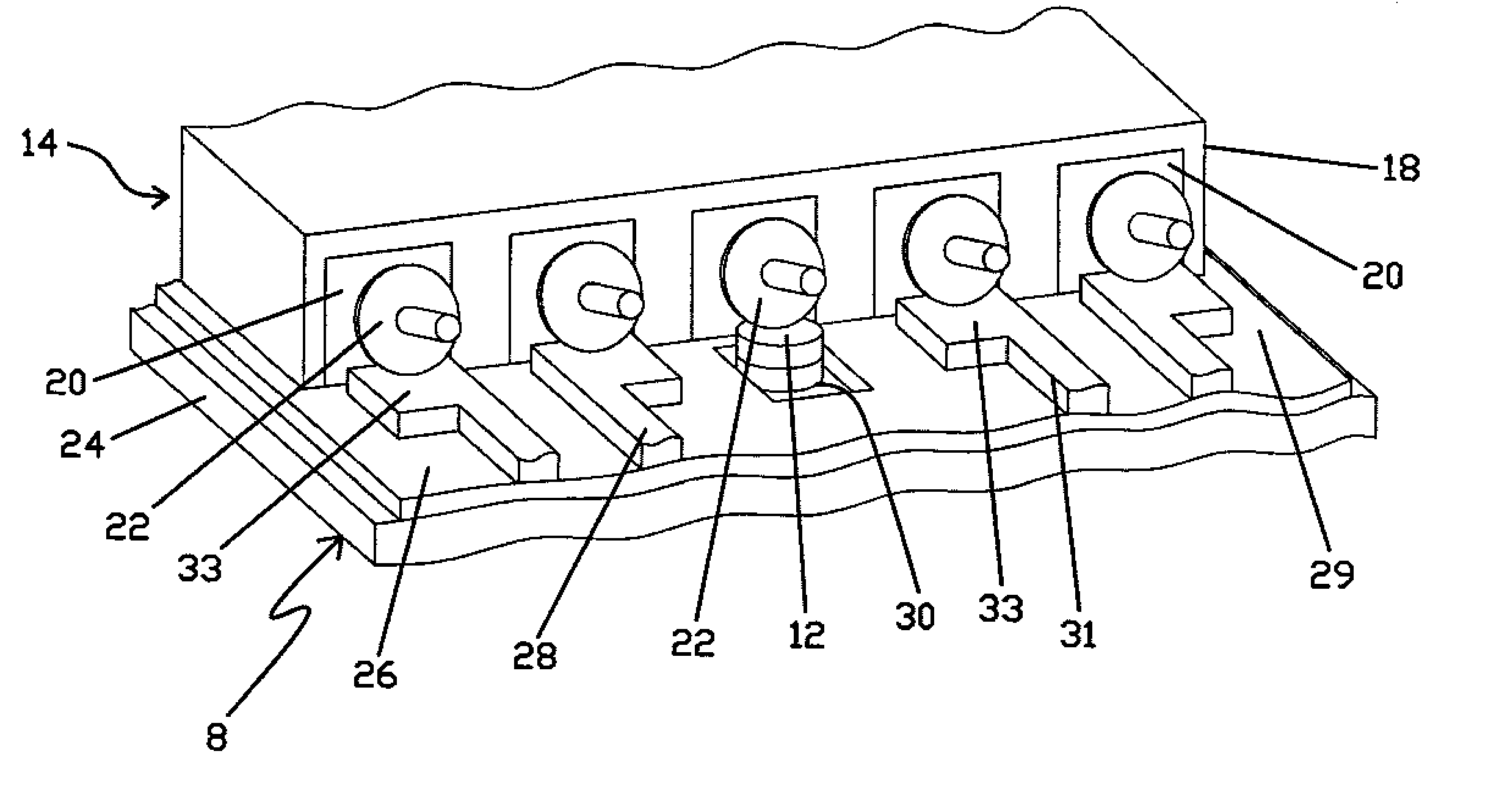
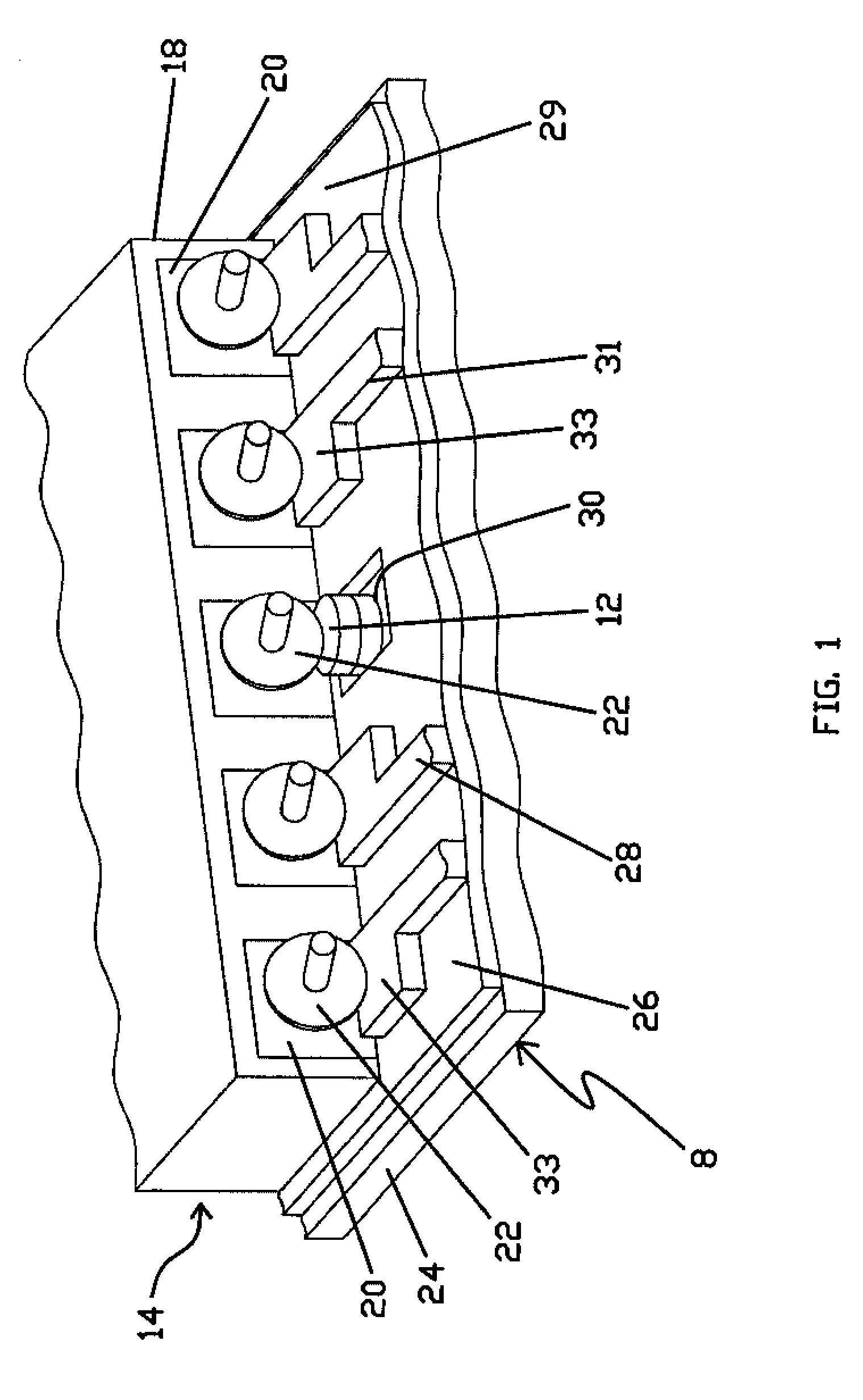
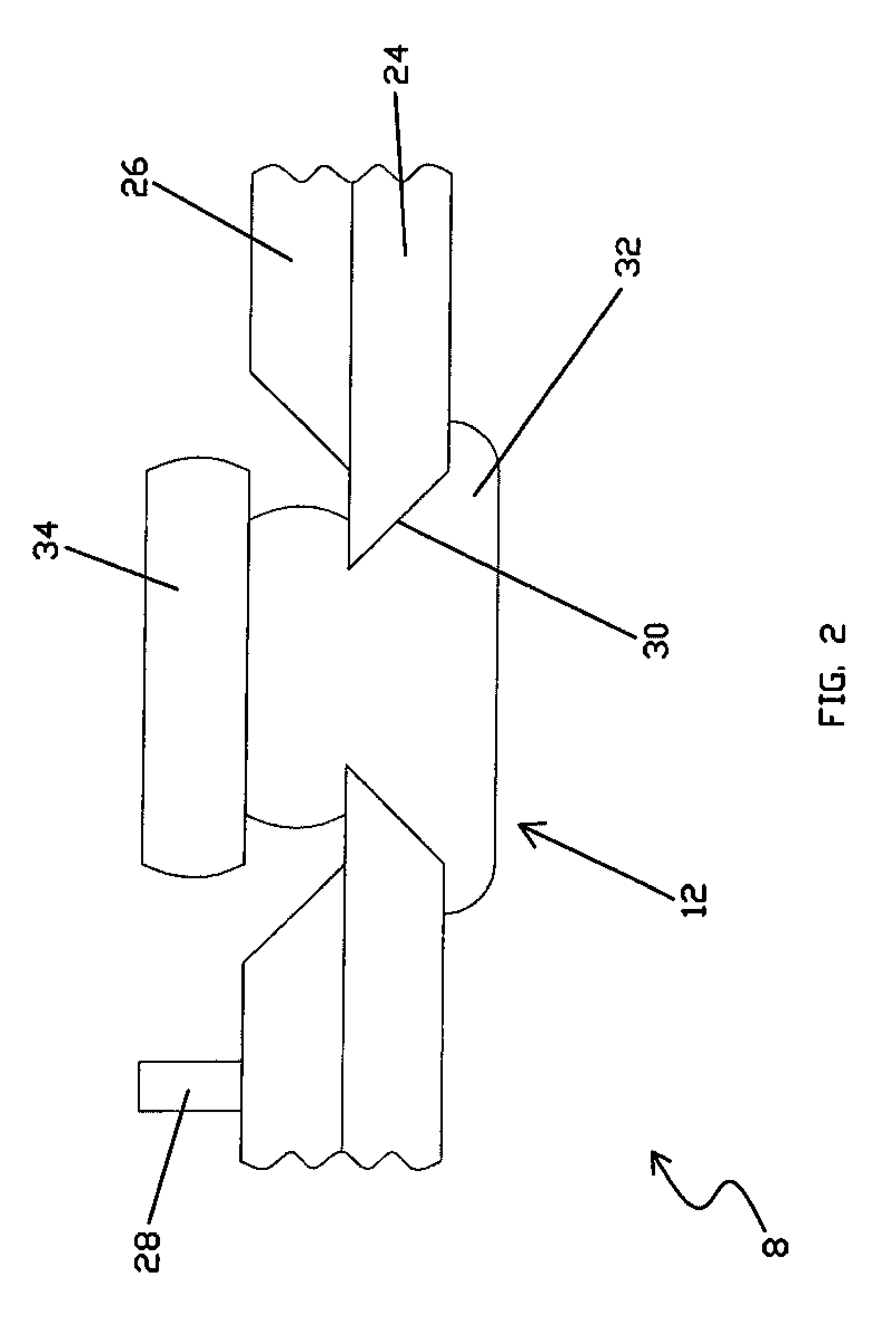
[0031]FIG. 1 is an illustration of a portion of the “lead” or “copper” side of a wireless or integrated lead flexure 8 (i.e., a suspension component) including a coined stud ground pad 12 in accordance with a first embodiment of the present invention. The flexure 8 is formed from multilayer structure. The multilayer structure may be formed through an additive process (e.g. deposition) or a subtractive process (e.g. etching) or some combination of additive and subtractive processes. In one embodiment, the flexure 8 may be formed from a laminated sheet of material. The flexure 8 includes a stainless steel layer 24 (i.e., spring metal layer) and a conductive metal or trace layer 28 separated by a dielectric insulator layer 26. The stainless steel layer 24 (a conductive material) is etched or formed into structural portions such as tongue 29 and side spring arms (not shown). The trace layer 28, which is often copper or copper alloy, is formed into a number of integrated traces or leads ...


PUM

PropertyMeasurementUnit
diameteraaaaaaaaaa
angleaaaaaaaaaa
diameteraaaaaaaaaa

Abstract

A method for forming an electrical interconnect to the spring metal layer in an integrated lead suspension or suspension component of the type having a multi-layer structure including a spring metal layer and a conductor layer separated by a dielectric insulator layer. The method includes forming an aperture through at least one of either the spring metal and conductor layers, and optionally through the dielectric layer, at an interconnect site. A first mass of malleable conductive metal is inserted into the aperture. The mass of metal is then coined to form a stud that engages at least the spring metal layer at the interconnect site.

Description

FIELD OF THE INVENTION [0001] This invention relates generally to integrated lead suspensions of the type used in magnetic disk drives or other dynamic data storage systems. More particularly, this invention relates to the forming of electrical interconnects in integrated lead suspension components formed as a multilayer structure, such as a laminate, including a stainless steel layer and a conductor layer separated by a dielectric insulator layer. BACKGROUND OF THE INVENTION [0002] Integrated lead suspensions for supporting a read / write head over a rotating disk in a magnetic data storage device are in widespread use and are well known. Such suspensions include a load beam (typically formed from a spring material such as stainless steel), a flexure (also typically formed from stainless steel) at a distal end of the load beam, conductors (also known as traces or leads and typically formed from copper), and a dielectric insulator layer between the conductor and adjacent stainless ste...

Claims


Application Information

Patent Timeline
Patent Type & Authority Applications(United States)
IPC IPC(8): G11B15/64G11B5/48G11B5/60G11B17/32G11B21/16G11B21/20H05K1/05H05K3/40H05K3/44
CPCG11B5/4846G11B5/486H05K1/056H05K3/4046H05K2203/0195H05K2201/09554H05K2201/0969H05K2201/10234H05K3/44G11B5/484
Inventor BENNIN, JEFFRY S.DANIELSON, REID C.HOUK, GALEN D.
Owner HUTCHINSON TECH
Why Eureka
Try Eureka