Machine for removing the sharp edge in plates in general and in particular in glass plates

Inactive Publication Date: 2008-04-17
Z BAVELLONI
5 Cites 2 Cited by

AI-Extracted Technical Summary

Problems solved by technology

As is known, in the case of plates which are subject to cutting, sharp edges are formed which can be dangerous and consequently must be removed.
Generally, known solutions produce an irregular removal of the sharpness of the arris along the entire length, a defect particularly observable in systems with a grinding wheel which is in a fixed position with respect to the glass pane, since the sharp edge of the plate has a linearity error caused by the preceding cutting operation and most of all there is a mismatch between the upper sharp edge and the lower sharp edge caused by the typical irregularity of glass plate cutting operations.
A...

Method used

[0050]During the working step, the spindles are made to oscillate in a vertical direction so that contact between the grinding wheel and the plate occurs by utilizing the entire band, having a conical profile, of the tangential grinding wheel, so that uniform wear is obtained, minimizing the need for replacement or redressing of the grinding wheel.
[0051]From what has been described above it is evident that the invention ...

Benefits of technology

[0011]The aim of the invention is to solve the problems described above by providing a machine for removing the sharp edge in plates in general and in glass plates ...

Abstract

A machine for removing sharp edge in plates in general and in glass plates in particular, comprising a frame for the support and advancement of a plate on which there is at least one station for arrissing an edge of the plate, the arrissing station comprising an upper tangential grinding wheel and a lower tangential grinding wheel which have a working profile which is inclined at 45° with respect to the rotation axis of the grinding wheels and can engage respectively an upper edge and a lower edge of the plate being worked.

Application Domain

Edge grinding machinesPlane surface grinding machines

Technology Topic

EngineeringMechanical engineering +1

Image

  • Machine for removing the sharp edge in plates in general and in particular in glass plates
  • Machine for removing the sharp edge in plates in general and in particular in glass plates
  • Machine for removing the sharp edge in plates in general and in particular in glass plates

Examples

  • Experimental program(1)

Example

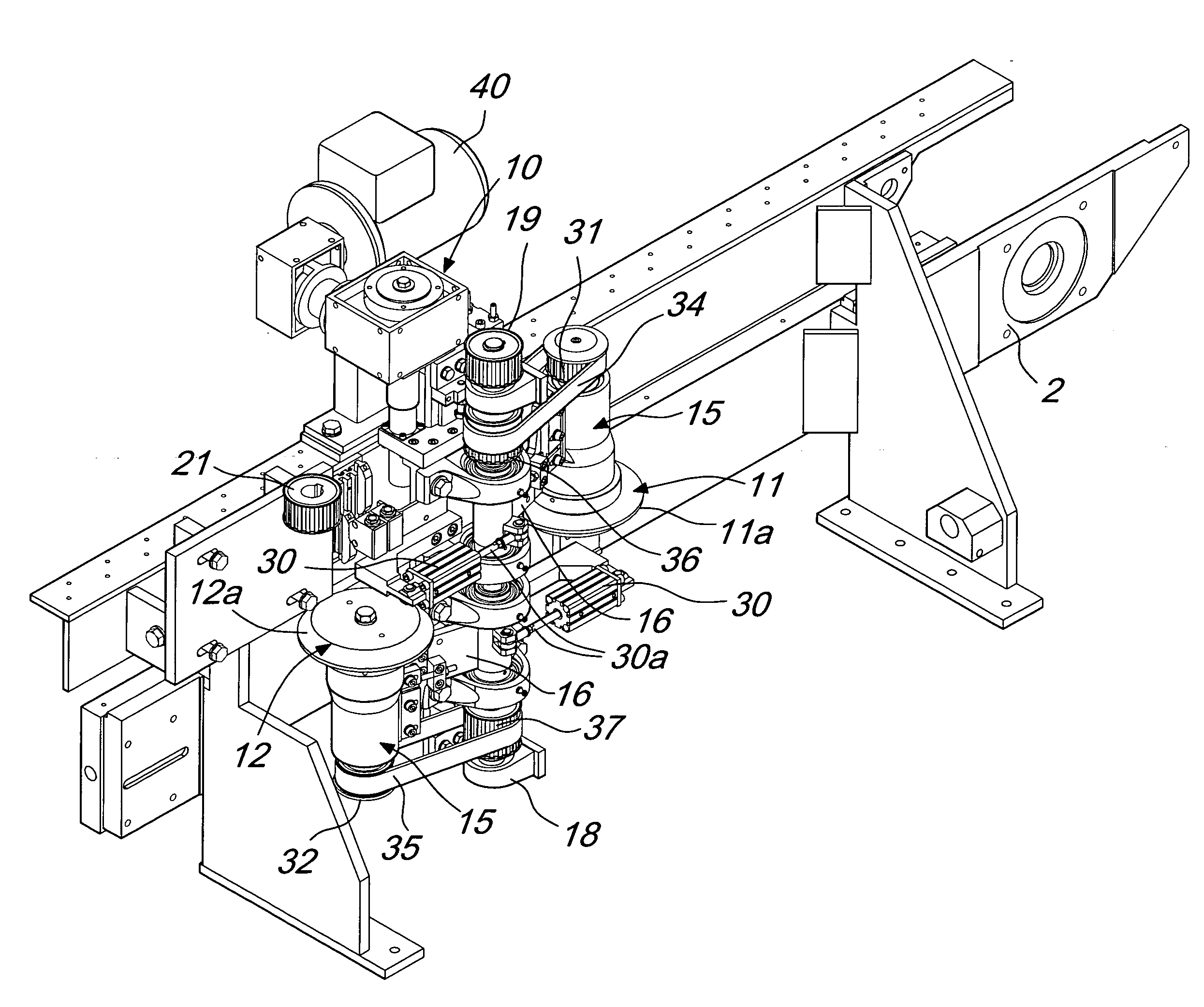
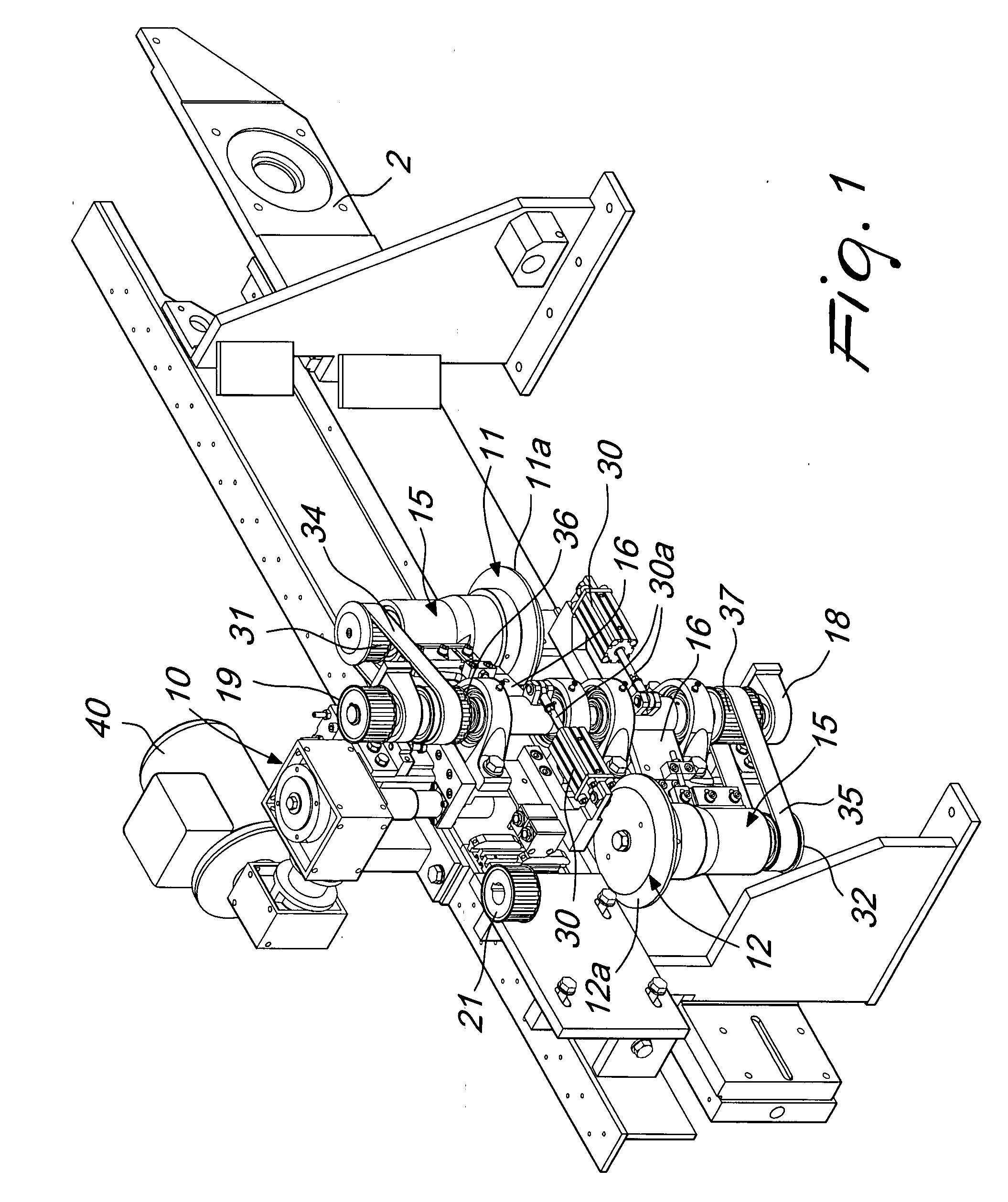
[0028]With reference to the figures, the machine for removing the sharp edge in plates in general and in glass plates in particular, generally designated by the reference numeral 1, comprises a frame 2 for the support and advancement of a plate 3 which is rested for example on a belt 4 which unwinds continuously.
[0029]At least one and preferably a plurality of arrissing stations, generally designated by the reference numeral 10, are typically provided at the edges of the plate.
[0030]Arrissing stations are usually provided on both of the advancement sides of the plate, which has a rectangular shape, and moreover the line provides for two machines with an interposed 90° transfer system, so that all the four edges of the plate are machined.
[0031]The drawing illustrates a single arrissing station, but of course, as mentioned earlier, the stations are typically four in number.
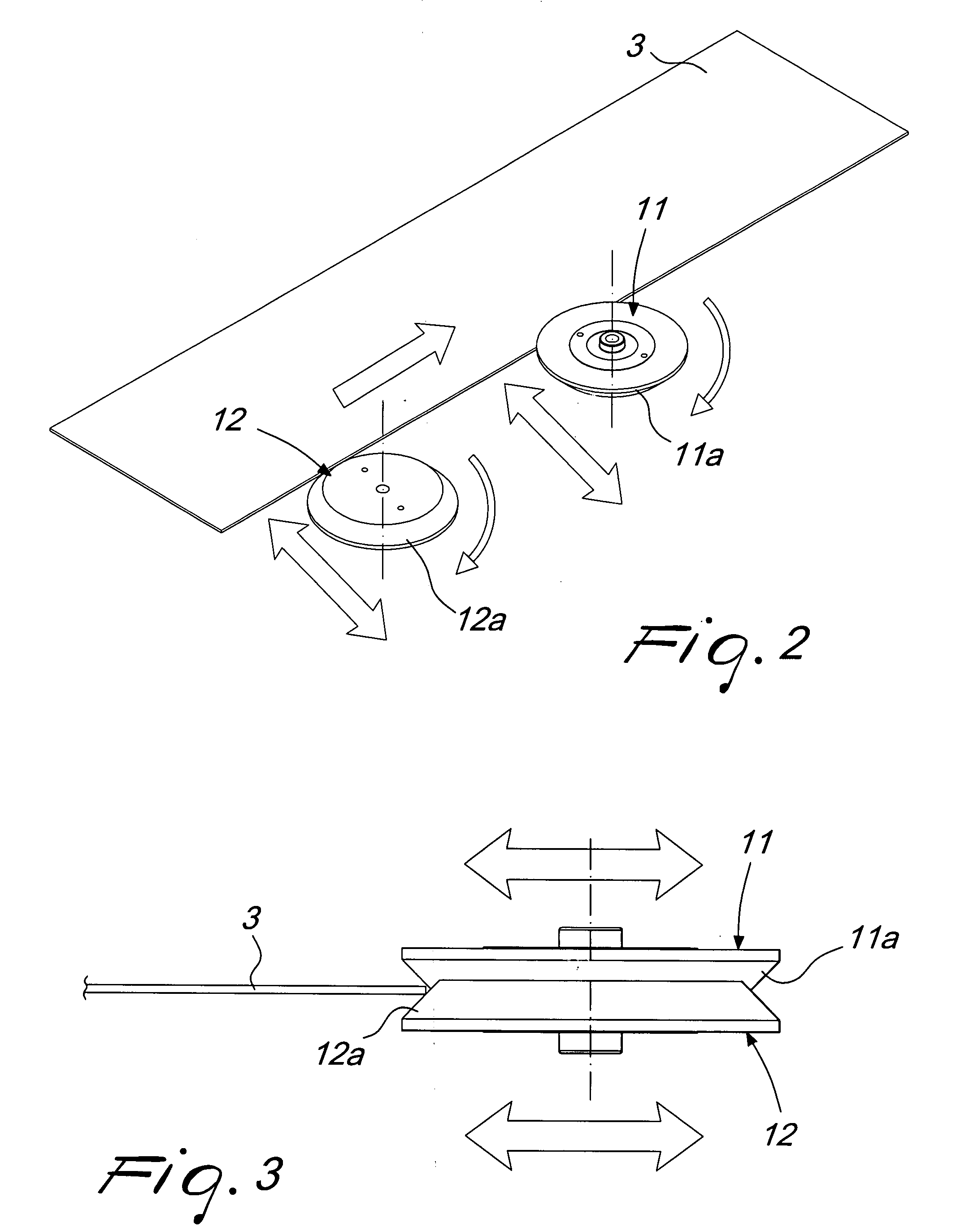
[0032]Each arrissing station 10 comprises an upper tangential grinding wheel 11 and a lower tangential grinding wheel 12.
[0033]The grinding wheels have a machining or working profile 11a and 12a which is inclined at 45° with respect to the axis of rotation.
[0034]Each grinding wheel can engage respectively the upper edge and the lower edge of the plate 3 being machined.
[0035]The grinding wheels 11 and 12 are supported by respective spindles, both designated by the reference numeral 15, which are connected by means of a cantilever support 16 with a vertical central shaft 17 which is supported by means of eyes 18 which are connected to the fixed structure.
[0036]The shaft 17 has an upper pulley 19 which by means of a belt 20 draws motion from a driving pulley 21 which is connected to a main motor 22.
[0037]Each cantilever support can oscillate about the central axis 17 and is pushed to machine by means of a pusher, which is advantageously provided by means of a pneumatic cylinder 30, the piston 30a whereof acts by pushing on the cantilever element so as to render active the sharp edge of the corresponding grinding wheel.
[0038]Each cantilever element supports, rigidly associated with the shaft of the corresponding grinding wheel, an upper grinding wheel pulley 31 and a lower grinding wheel pulley 32 on which an upper grinding wheel belt 34 and a lower grinding wheel belt 35 respectively unwind, said belts winding around respective upper and lower central pulleys 36 and 37 which are keyed on the central shaft 17 which draws motion from the motor 22.
[0039]With this type of connection, the grinding wheels are turned about their own axis and the cantilever element is structured so as to move the inclined edges of the corresponding grinding wheels 11 and 12 so that they work the upper and lower arrises of the plate 3.
[0040]To allow uniform wear of the grinding wheel, there is provided a system for oscillating along a vertical direction, which comprises an oscillation motor 40 which is connected, for example by means of a nut screw coupling 41, to the panel 42 which can slide with respect to the frame and supports the cantilever elements, imparting thereto a reciprocating translational motion along the vertical axis, so that the point of the inclined working profile of the grinding wheels is changed in each instance.
[0041]With this arrangement, only the cantilever elements with the corresponding spindles are moved, and, for this purpose the pulleys 36 and 37 have an increased axial extension with respect to the width of the corresponding belt, so as to adapt to the variation in the placement of the pulleys 31 and 32 connected to the spindles 15.
[0042]This type of connection allows to have reduced moving masses, since the motors, due to the rotation of the grinding wheel and to the oscillation along the vertical direction, remain in a fixed position.
[0043]To allow correct placement of the grinding wheels with respect to the edge of the plate, especially in the initial step, positioning cams are provided which are constituted by an upper cam and by a lower cam, both designated by the reference numeral 50, which engage an abutment roller 51, which is associated with the respective cantilever element, so as to provide an element for stopping the advancement of the grinding wheel toward the plate, therefore providing exact positioning even in the initial step of the engagement between the grinding wheel and the plate.
[0044]It should be added that the cam 50 arranged in an upper region can be connected to a vertical positioning device, which is provided for example by a piston 60 which changes the relative position of the cam 50 arranged above according to the thickness of the plate.
[0045]With the apparatus described above, the plate to be worked is engaged by the conveyor belt 4 and, during its advancement, encounters the arrissing stations, usually provided one for each side.
[0046]The lower spindle, with its grinding wheel turning, interferes with the plate to an extent which is preset by the contact of the cantilever system which is adjusted by the arrangement of the cam 50.
[0047]Contact with the plate causes the movement of the spindle to the balancing point between the grinding force and the force of the pneumatic cylinder that pushes the cantilever element so that the lower arris of the edge is machined.
[0048]The plate, in its advancement, then encounters the upper spindle, which machines the upper sharp edge in the same manner described above.
[0049]When the plate abandons the spindles, the cantilever element moves the cam so that it abuts against the abutment roller and is positioned for subsequent work.
[0050]During the working step, the spindles are made to oscillate in a vertical direction so that contact between the grinding wheel and the plate occurs by utilizing the entire band, having a conical profile, of the tangential grinding wheel, so that uniform wear is obtained, minimizing the need for replacement or redressing of the grinding wheel.
[0051]From what has been described above it is evident that the invention achieves the intended aim and objects, and in particular the fact is stressed that a machine is provided in which the sharp edge of the plate is arrissed by using two distinct tangential grinding wheels with a 45° contour, achieving uniform work thanks to the fact that such grinding wheels are supported by respective cantilever elements which allow to adapt the mutual positioning between the grinding wheel and the plate.
[0052]Another important aspect of the invention consists in that the control motors of the grinding wheels and of the vertical oscillation do not affect the moving masses, which are constituted exclusively by the cantilever elements which are thus positioned correctly with respect to the edge being worked thanks to the presence of the cam elements and of the constant thrust applied by the pneumatic pistons which keep the grinding wheels in working contact against the edge.
[0053]The invention thus conceived is susceptible of numerous modifications and variations, all of which are within the scope of the appended claims.
[0054]All the details may further be replaced with other technically equivalent elements.
[0055]In practice, the materials used, as well as the contingent shapes and dimensions, may be any according to requirements.
[0056]The disclosures in Italian Patent Application No. MI2006A001986 from which this application claims priority are incorporated herein by reference.

PUM

no PUM

Description & Claims & Application Information

We can also present the details of the Description, Claims and Application information to help users get a comprehensive understanding of the technical details of the patent, such as background art, summary of invention, brief description of drawings, description of embodiments, and other original content. On the other hand, users can also determine the specific scope of protection of the technology through the list of claims; as well as understand the changes in the life cycle of the technology with the presentation of the patent timeline. Login to view more.
Why Eureka
Try Eureka