Supporting a decoding of frames

a decoding and frame technology, applied in the field of support of frames, can solve the problems of reducing sound quality, packets and included audio frames are considered lost, and jitter in the network, and achieve the effect of reducing the negative effect on quality

Inactive Publication Date: 2008-04-17
NOKIA TECHNOLOGLES OY
View PDF7 Cites 19 Cited by
  • Summary
  • Abstract
  • Description
  • Claims
  • Application Information

AI Technical Summary

Benefits of technology

[0013]The invention proceeds from the consideration that the mentioned “late frame processing” is computationally very complex. Further, when considering the practical implementation of an adaptive jitter buffer, a late-arriving frame indicates in many cases that the buffering delay is too short, for example due to a changing transmission delay or due to changing jitter conditions.

Problems solved by technology

In addition to packet loss conditions, network jitter is a major hurdle especially for conversational speech services that are provided by means of packet switched networks.
Thus, if some packets comprising audio frames arrive only after the audio frames are needed for decoding and further processing, those packets and the included audio frames are considered as lost due to a too late arrival.
Obviously, extensive error concealment will reduce the sound quality as well, though.
A jitter buffer introduces, however, an additional delay component, since the received packets are stored before further processing.
This increases the end-to-end delay.
A jitter buffer, from which frames are extracted with a fixed rate due to a fixed decoding timing, is inevitably a compromise between a low end-to-end delay and a low amount of delayed frames, and finding an optimal tradeoff is not an easy task.
Using a fixed decoding timing with the initial buffering delay that is set to a sufficiently large value to cover the jitter according to an expected worst case scenario would keep the amount of delayed frames in control, but at the same time there is a risk of introducing an end-to-end delay that is too long to enable a natural conversation.
Therefore, applying a fixed buffering scheme is not the optimal choice in most audio transmission applications operating over a packet switched network, for example in Voice over Internet Protocol (VoIP) over the 3GPP IP Multimedia Subsystem (IMS).
In case the transmission delay seems to increase or the jitter is getting worse, the buffering delay is increased to meet the network conditions.
One of the challenges in adaptive jit

Method used


Image

  • Supporting a decoding of frames
  • Supporting a decoding of frames
  • Supporting a decoding of frames

Examples


Embodiment Construction

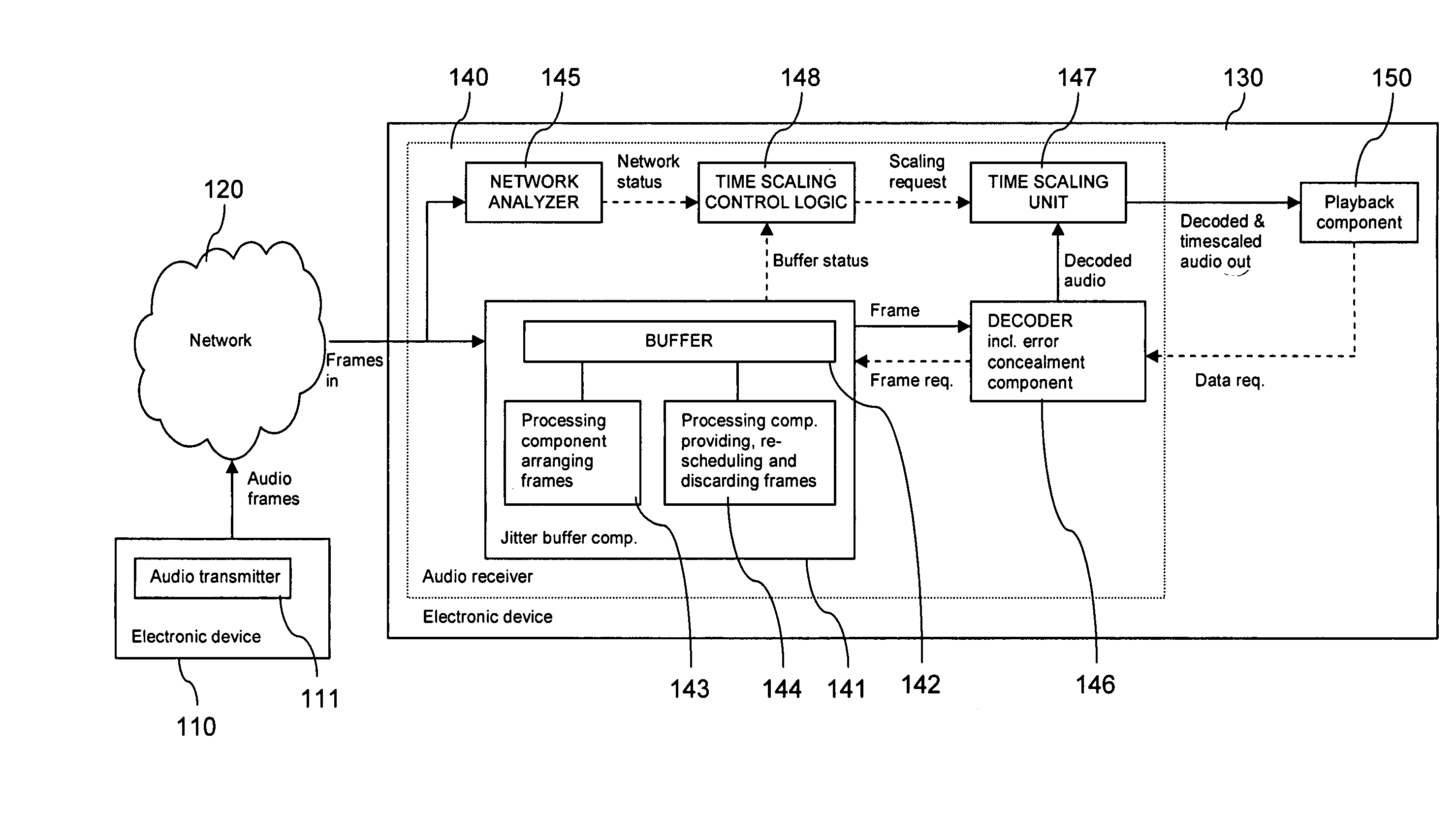
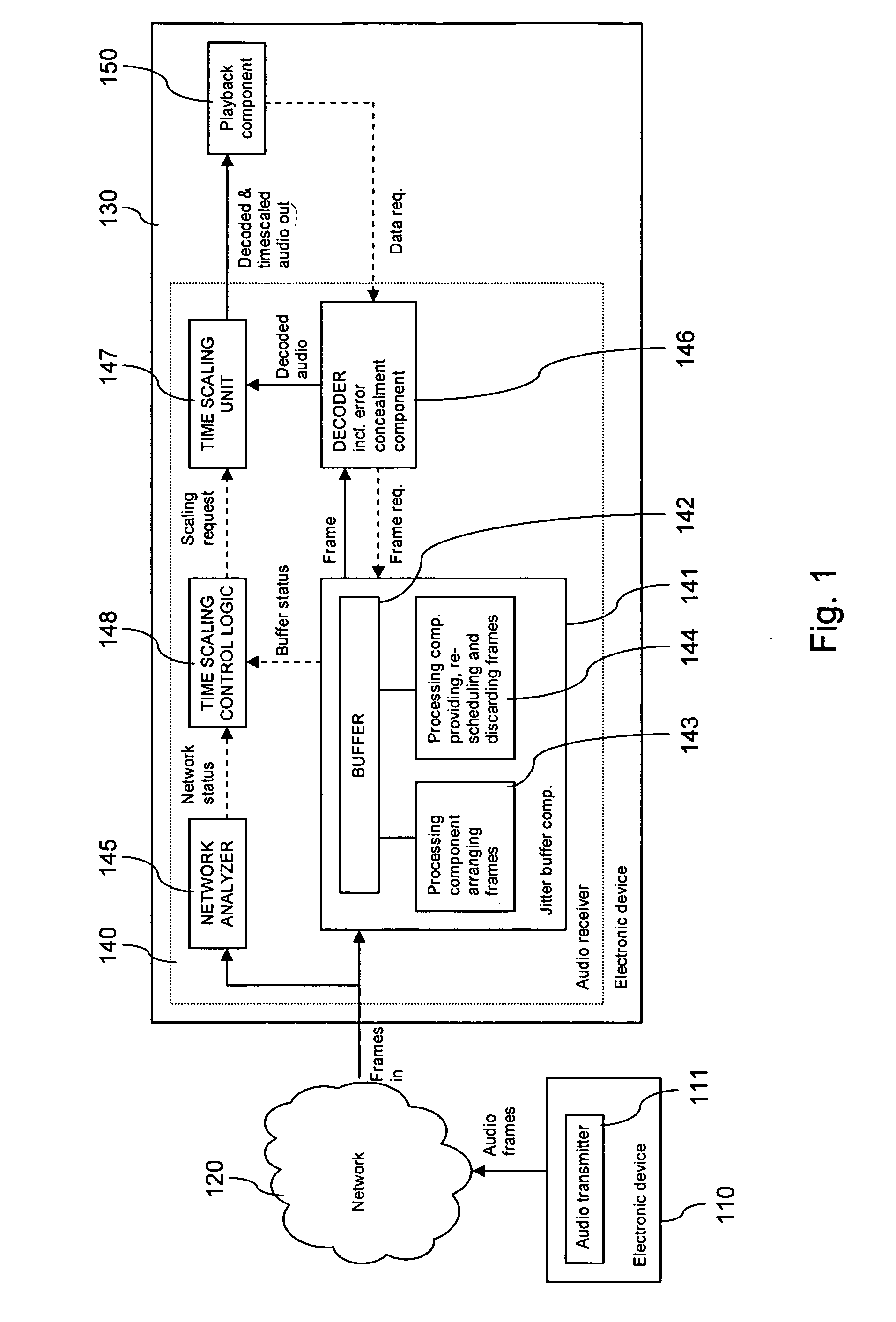
[0038]FIG. 1 is a schematic block diagram of an exemplary system, which enables a handling of audio frames arriving too late for a normal decoding in accordance with an embodiment of the invention.

[0039]The system comprises an electronic device 110 with an audio transmitter 111, a packet switched communication network 120 and an electronic device 130 with an audio receiver 140. It is to be understood that the electronic device 110 may equally comprise a corresponding audio receiver 140 and that the electronic device 130 may equally comprise a corresponding audio transmitter 111. The packet switched communication network 120 can be or comprise for example the Internet, and it can be accessed by both electronic devices 110, 130.

[0040]The input of the audio receiver 140 of electronic device 130 is connected within the audio receiver 140 on the one hand to a jitter buffer component 141 and on the other hand to a network analyzer 145. The jitter buffer component 141 comprises in addition...


PUM


Abstract

For supporting a decoding of encoded frames, which belong to a sequence of frames received via a packet switched network, it is detected whether a particular encoded frame has been received after a scheduled decoding time for the particular encoded frame and before a scheduled decoding time for a next encoded frame. In case the particular encoded frame is detected to have been received after its scheduled decoding time and before the scheduled decoding time for the next encoded frame, the particular encoded frame is re-scheduled to be decoded at the scheduled decoding time for the next encoded frame.

Description

FIELD OF THE INVENTION[0001]The invention relates to the support of a decoding of frames, which belong to a sequence of frames and which are received via a packet switched network.BACKGROUND OF THE INVENTION[0002]Encoded frames may be transmitted from a transmitter to a receiver via a packet switched network, such as the Internet.[0003]For a transmission of voice, for example, speech frames may be encoded at a transmitter, transmitted via a packet switched network, and decoded again at a receiver for presentation to a user. During periods when the transmitter has no active speech to transmit, the normal transmission of speech frames may be switched off. The transmitter may generate during these periods a set of comfort noise parameters describing the background noise that is present at the transmitter. These comfort noise parameters may be sent to the receiver in additional silence descriptor (SID) frames. The receiver may then use the received comfort noise parameters to synthesize...

Claims


Application Information

Patent Timeline
IPC IPC(8): H03M13/00
CPCH04L49/90H04L47/10H04L49/9023
Inventor LAKANIEMI, ARIOJALA, PASI S.
Owner NOKIA TECHNOLOGLES OY
Why Eureka
Try Eureka