System and Method of High-Speed Image-Cued Triggering

a high-speed digital camera and image cue technology, applied in the field of high-speed “ smart” digital cameras, can solve the problems of limited on-board storage capacity of high-speed digital cameras, too expensive long-term storage for many applications, and high cost of digital memory

Inactive Publication Date: 2008-04-24
SOUTHERN VISION SYST
View PDF7 Cites 11 Cited by
  • Summary
  • Abstract
  • Description
  • Claims
  • Application Information

AI Technical Summary

Benefits of technology

[0015] For purposes of summarizing the invention, certain aspects, advantages, and novel features of the invention have been described herein. It is to be understood that not necessarily all such advantages may be achieved in accordance with any one particular embodiment of the invention. Thus, the invention may be embodied or carried out in a manner that achieves or optimizes one advantage or group of advantages as taught herein without necessarily achieving other advantages as may be taught or suggested herein.

Problems solved by technology

However, the costs associated with digital memory make long-time storage too expensive for many applications.
High-speed digital cameras have limited on-board storage capacity because of the high rate of data transfer and because of the size, power consumption, and cost associated with available digital memories.
In addition, even though the camera stores the entire image, there is relevant information in only a part of the image, leading to inefficient use of memory.
High-speed digital cameras are especially impacted by this inefficiency because of the large data-rates needed for transferring imagery and the high costs of digital storage.
In addition, digital cameras used with conventional proximity sensors risk missing an event of interest.

Method used


Image

  • System and Method of High-Speed Image-Cued Triggering
  • System and Method of High-Speed Image-Cued Triggering
  • System and Method of High-Speed Image-Cued Triggering

Examples


Embodiment Construction

[0022] The present invention and its advantages are best understood by referring to the drawings. The elements of the drawings are not necessarily to scale, emphasis instead being placed upon clearly illustrating the principles of the invention.

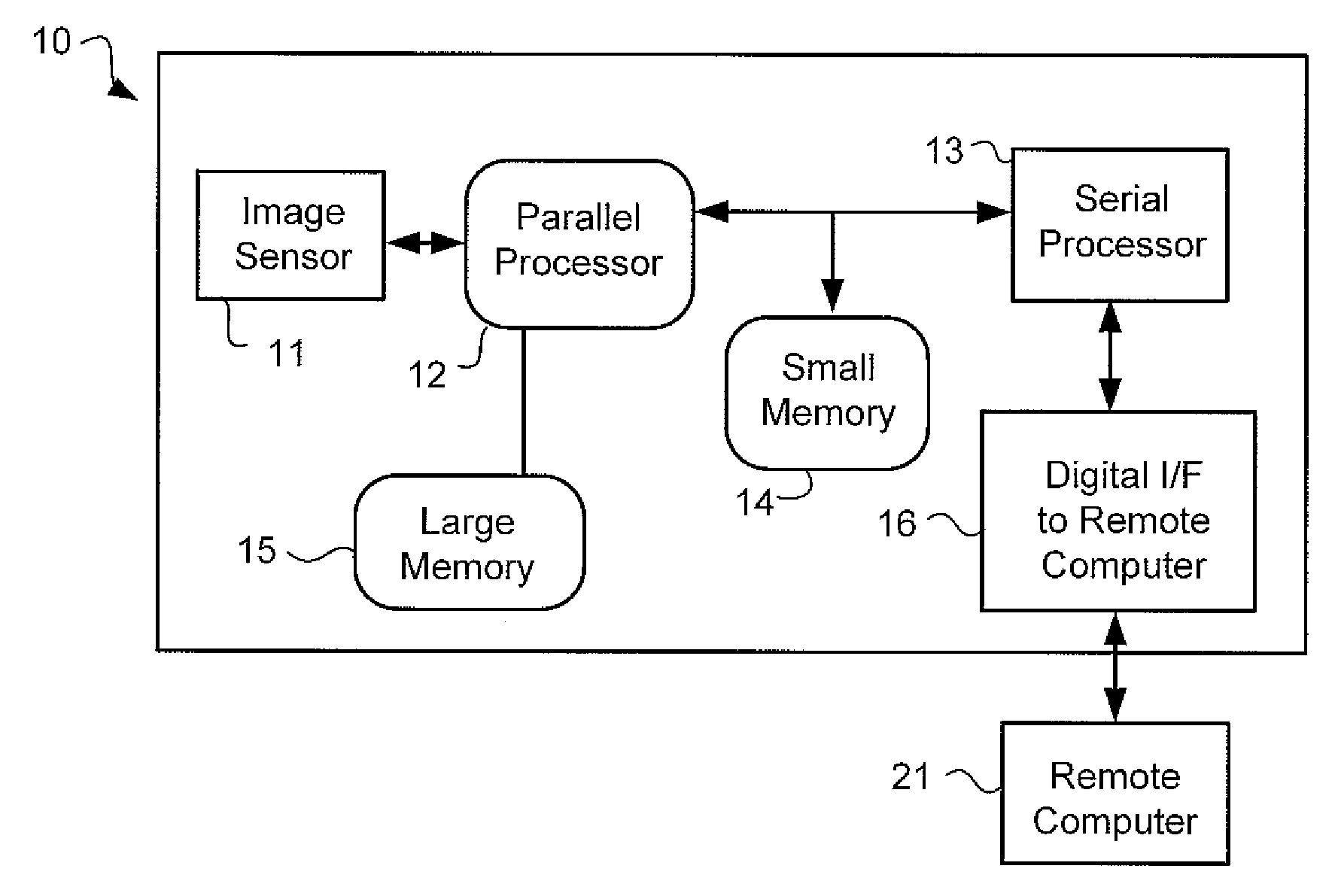
[0023] One embodiment of the camera 10 is represented schematically in FIG. 1. Parallel processor 12 and serial processor 13 perform the processing functions for the camera 10. There are two common techniques for processing high-speed imagery: “pipeline” and “parallel.” The pipeline technique adds latency to the processing time by requiring that the “pipeline” be filled before processing begins. Once filled, each sequential operation on the pipeline represents final processing of an image pixel. The parallel technique utilizes multiple processors running in parallel to accomplish image processing. An extreme example of this is a processor for each image pixel. However, this is unrealistic given the status of current technology, and some reas...


PUM


Abstract

A high-speed digital camera system and method for processing high-speed image data is claimed. The method comprises generating images with at least 3×105 pixels at greater than 60 frames-per-second with an image sensor, downloading an image; defining an area of interest in the downloaded image comprising a plurality of adjacent pixels in which an event of interest is expected to occur, defining at least one threshold level for all pixels in the plurality; uploading the defined threshold level to a processor, retrieving pixel data in real time from the image sensor, and comparing the pixel data to the defined threshold levels. A trigger is set when the threshold levels are exceeded and the camera records the event of interest and stores it in camera memory for outputting to a remote computer.

Description

REFERENCE TO RELATED APPLICATIONS [0001] This application is a continuation-in-part of and claims priority to Non-provisional patent application U.S. Ser. No. 11 / 582,892, entitled “System and Method of High-Speed Image-Cued Triggering” and filed on Oct. 18, 2006, which is fully incorporated herein by reference.FIELD OF THE INVENTION [0002] The present invention relates generally to the field of high-speed “smart” digital cameras, and specifically to a method of assessing imagery real-time in order to determine subsequent processing tasks to be performed inside the camera at frame-rates in excess of 60 Hz. BACKGROUND OF THE INVENTION [0003] Digital cameras using rectangular arrays of photo-detector picture elements (pixels) are well-known in the art and are replacing film cameras in the fields of motion capture, bio-analysis, ordnance characterization, and missile development. Digital storage devices currently allow storage of terabyte (1012 bytes) size files resulting in several min...

Claims


Application Information

Patent Timeline
Patent Type & Authority Applications(United States)
IPC IPC(8): H04N5/225
CPCH04N5/232H04N5/772H04N5/77H04N5/335H04N25/00
Inventor WHITEHEAD, CHARLES A.WIRTH, GREGORY J.
Owner SOUTHERN VISION SYST
Why Eureka
Try Eureka