Hollow needle assembly

a needle and needle body technology, applied in the field of hollow needle assembly, can solve the problems of inability to accurately analyze blood samples, delay in actual analysis of blood samples, and unnecessary blood handling, so as to minimize the risk of injury and blood contamination, minimize the discomfort of the patient, and avoid injury

Inactive Publication Date: 2008-04-24
CHROMEDX
View PDF2 Cites 9 Cited by
  • Summary
  • Abstract
  • Description
  • Claims
  • Application Information

AI Technical Summary

Benefits of technology

[0015]According to a third aspect of an embodiment of the invention there is provided a hollow needle assembly comprising:a) a needle constructed of one or more than one part, the needle comprising a shaft having a lumen connecting a sharp open end to a second end, and a hub having a passage, the hub also having a front end and a back end, the back end comprising analyte measurement means, and the passage having a front side located at the front end and a blunt open end located at the back end, wherein the second end of the shaft is mounted in the front side of the passage, and a flow path is defined along the lumen and the passage, beginning at the sharp open end and terminating at the blunt open end, and wherein the blunt open end coincides with a vent of the analyte measurement means; andb) a barrel constructed of one or more than one part, having an open anterior end through which a portion of the shaft of the needle passes, and an open posterior end through which a portion of the hub of the needle passes, the barrel comprising an internal chamber for housing at least a portion of the needle, wherein the barrel facilitates extension and concealment of the sharp open end.
[0016]Some embodiments of the invention provide a needle with a sharp open end and a blunt open end, housed in a barrel with an open anterior end and an open posterior end. The barrel can travel along the hub of the needle, for extending the needle for insertion into a blood vessel, and for retracting the needle into the barrel to avoid injury. The blunt open end can be fluidly connected to the inlet of a measurement apparatus, so that the blood can flow directly into the measurement apparatus, eliminating the traditional step of transferring the blood from a syringe to the measurement apparatus. The hollow needle assembly can remain attached to the measurement apparatus because of its small size, and the engagement of an optional safety cap to the open anterior end of the barrel, minimizes the risk of injury and blood contamination. Because a small blood sample is required, a very small needle shaft can be used, minimizing the discomfort experienced by the patient.

Problems solved by technology

In general, conventional methods of collecting and analyzing blood leads to inevitable delays, unnecessary handling of the blood and the introduction of contaminants, which are all known sources of analysis error.
The eventual transfer of blood between vessels delays the actual analysis of the blood sample and also exposes the blood sample to contaminants.
Because these instruments are large and expensive, they are usually located in central laboratories.
Biosensor technology is also limited by the blood parameters it can measure.
For example, biosensors are not currently available for measuring the Hb species measured by the available co-oximeters.
There are many benefits in providing these blood tests near or at the point of care of patients, but these are usually limited by the size and cost of the diagnostic measurement instruments.
Arterial blood must be collected by a doctor or a specially-trained technician, using a syringe, because of a number of inherent difficulties associated with the complicated collection procedure.
Notably, the collection of arterial blood is far more painful, difficult and dangerous for a patient, than the collection of venous blood.

Method used


Image

  • Hollow needle assembly
  • Hollow needle assembly
  • Hollow needle assembly

Examples


first embodiment

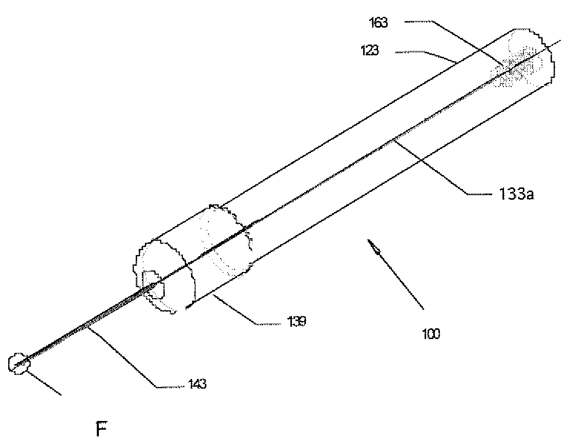
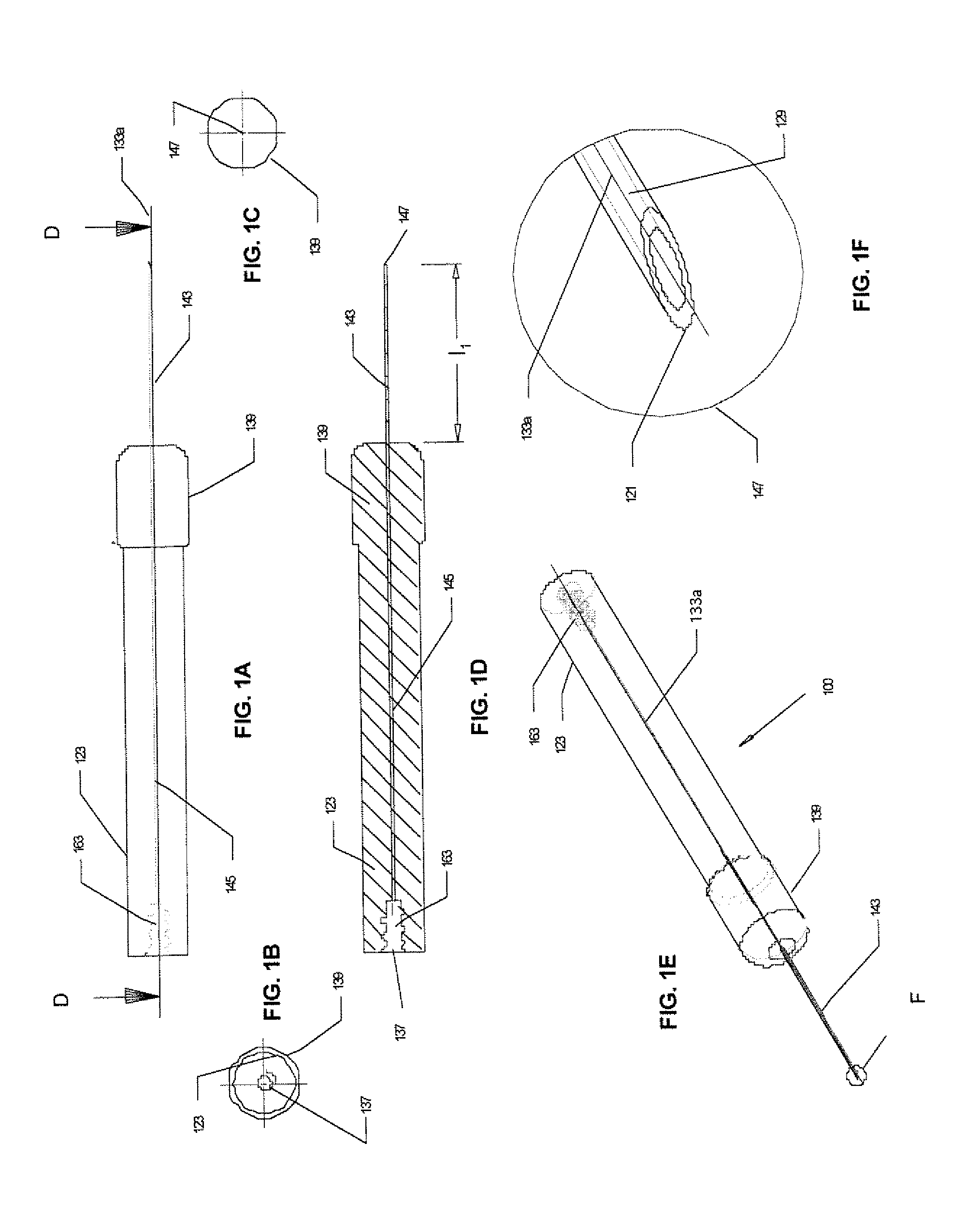
[0085]Referring to FIG. 1A, shown is a schematic drawing illustrating a top view of a needle 100 for a hollow needle assembly according to the invention; FIG. 1B illustrates a left side-view of the apparatus shown in FIG. 1A; FIG. 1C illustrates a right side-view of the apparatus shown in FIG. 1A; FIG. 1D illustrates a cross-sectional view through the apparatus shown in FIG. 1A along line D-D; FIG. 1E illustrates a perspective view of the apparatus shown in FIG. 1A; and FIG. 1F illustrates a detailed view of the detail F shown in FIG. 1E.

[0086]Still referring to FIG. 1, the needle 100 comprises a shaft 143 and a hub with a front end 139 and a back end 123. The shaft 143 has a sharp open end 147 and a second end, which is mounted in the passage 145 of the hub. A detailed view of the sharp open end 147 (detail F in FIG. 1E) is shown in FIG. 1F. The sharp open end 147 is usually the beveled end of the shaft, which is usually a hollow metal tube. It should be understood that the sharp o...

second embodiment

[0089]Referring to FIG. 3A, shown is a schematic drawing illustrating a top view of a needle for a hollow needle assembly according to the invention; FIG. 3B illustrates a left side-view of the apparatus shown in FIG. 3A; FIG. 3C illustrates a right side-view of the apparatus shown in FIG. 3A; FIG. 3D illustrates a cross-sectional view through the apparatus shown in FIG. 3A along line D-D; FIG. 3E illustrates a perspective view of the apparatus shown in FIG. 3A; and FIG. 3F illustrates an alternative perspective view of the apparatus shown in FIG. 3A. The apparatus 100 illustrated in FIG. 3 is similar to the apparatus 100 illustrated in FIG. 1, and accordingly, elements common to both share common reference numerals. The primary differences, illustrated in FIG. 3, are that the back end of the hub 139 contains external threads 173 for mating with internal threads 175 in a complementary barrel 200 shown in FIG. 4, and the blunt open end 137 is housed in a tapered projection 171, where...

fourth embodiment

[0094]Referring to FIG. 8A, shown is a schematic drawing illustrating a top view of the needle and barrel assembly 700, as shown in FIG. 7, with the needle concealed inside the barrel, and with an optional safety cap 189 engaged, according to the invention; FIG. 8B illustrates a left side-view of the apparatus shown in FIG. 8A; FIG. 8C illustrates a right side-view of the apparatus shown in FIG. 8A; and FIG. 8D illustrates a cross-sectional view through the apparatus shown in FIG. 8A along line D-D. The apparatus 700 illustrated in FIG. 8 is similar to the apparatus 500 illustrated in FIG. 7, and accordingly, elements common to both share common reference numerals. The primary differences, illustrated in FIG. 8, are that the needle shaft 143 is withdrawn inside the barrel 200, and a safety cap 189 is fitted over the open anterior end 159 of the barrel, to further protect the user from accidental injury.

[0095]Referring to FIG. 9A, shown is a schematic drawing of an apparatus 800, ill...


PUM


Abstract

Some embodiments of the invention provide a needle with a sharp open end and a blunt open end, housed in a barrel with an open anterior end and an open posterior end. The barrel can travel along the hub of the needle, for extending the needle for insertion into a blood vessel, and for retracting the needle into the barrel to avoid injury. The blunt open end can be fluidly connected to the inlet opening of a measurement apparatus, so that the blood can flow directly into the measurement apparatus, eliminating the traditional step of transferring the blood from a syringe to the measurement apparatus. The hollow needle assembly can remain attached to the measurement apparatus because of its small size, and the engagement of an optional safety cap to the open anterior end of the barrel, minimizes the risk of injury and blood contamination. Because a small blood sample is required, a very small needle shaft can be used, minimizing the discomfort experienced by the patient.

Description

FIELD OF THE INVENTION[0001]The invention relates to a hollow needle assembly for transferring fluid from one site to another. In particular, the invention relates to the needle, and a barrel that facilitates extension and concealment of the sharp open end of the needle.BACKGROUND OF THE INVENTION[0002]There are many medical diagnostic tests that require a blood sample. In general, conventional methods of collecting and analyzing blood leads to inevitable delays, unnecessary handling of the blood and the introduction of contaminants, which are all known sources of analysis error. More specifically, as per convention, a blood sample is typically withdrawn using one instrument / vessel and then transferred into another vessel for analysis. For example, a syringe is used to obtain a relatively large blood sample that is later injected into measuring instruments or disposable cartridges of measuring instruments. Syringe extraction of blood is beneficial in circumstances where several mill...

Claims


Application Information

Patent Timeline
IPC IPC(8): A61B5/153A61M5/32
CPCA61B5/1411A61M5/3271A61M5/326A61B5/15003A61B5/150213A61B5/150251A61B5/150389A61B5/150503A61B5/150603A61B5/150633A61B5/150717A61B5/153
Inventor SAMSOONDAR, JAMES
Owner CHROMEDX
Why Eureka
Try Eureka