
Method for simultaneously slicing at least two cylindrical workpieces into a multiplicity of wafers

a technology of multiplicity and workpiece, which is applied in the direction of manufacturing tools, metal sawing devices, grinding machine components, etc., can solve the problems of difficult placement of separating disks according to the method described in this application, the edge is very sharp, and the stack is not secured against the lateral, so as to achieve the maximum prevent edge damage, and improve the utilization of gang length

Active Publication Date: 2008-05-01
SILTRONIC AG
View PDF8 Cites 7 Cited by
  • Summary
  • Abstract
  • Description
  • Claims
  • Application Information

AI Technical Summary

Benefits of technology

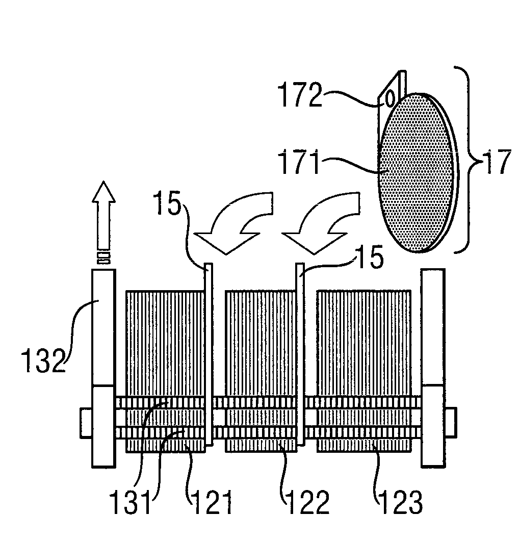
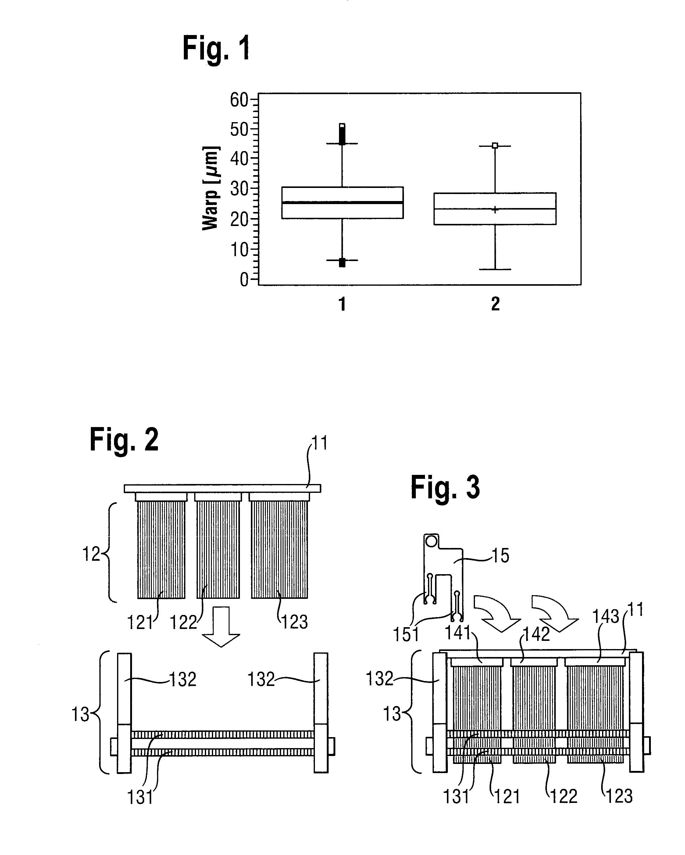
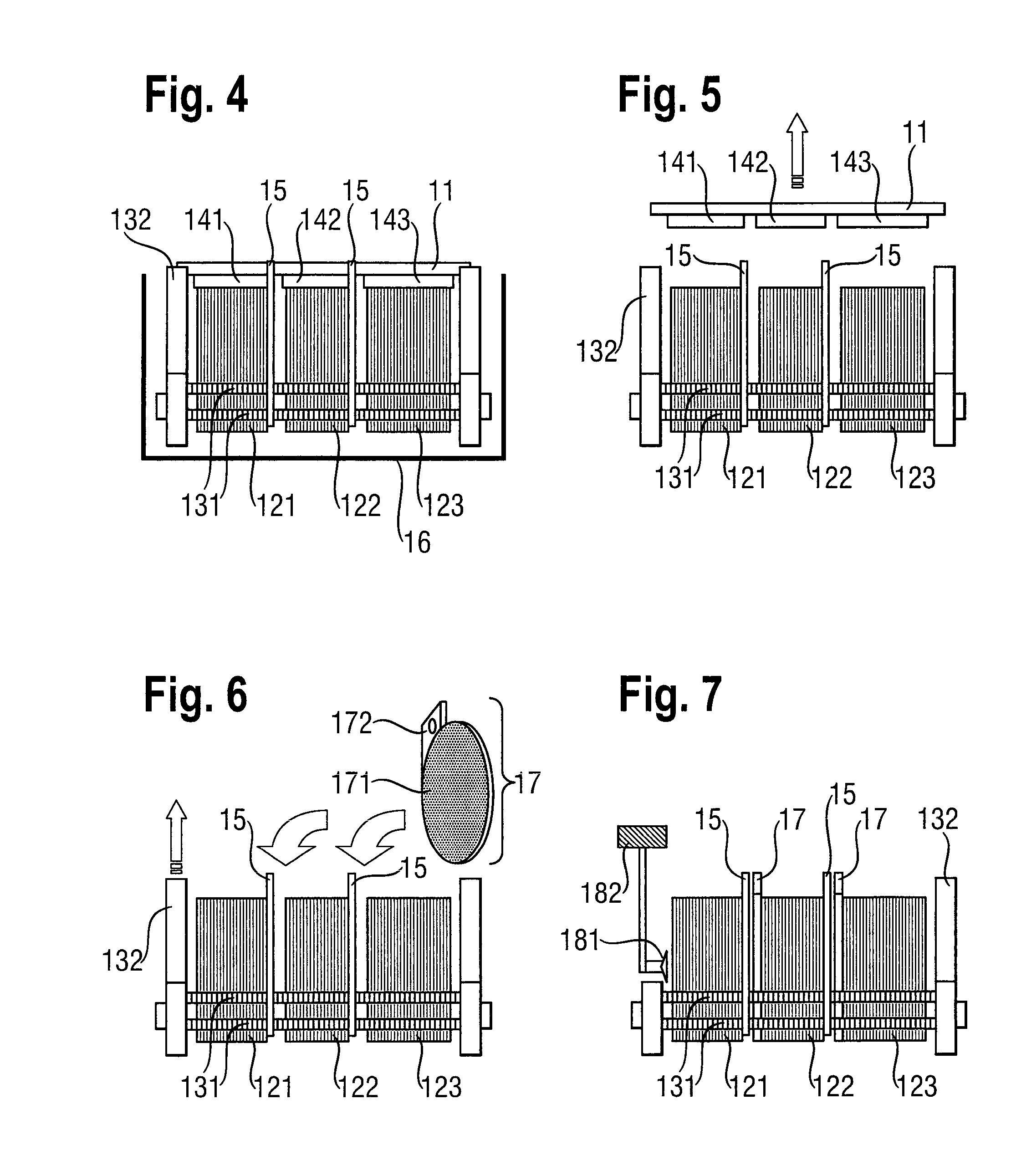
[0010]It was therefore an object of the invention to improve the utilization of the available gang length of a multi wire saw. It was also an object to avoid damaging the wafers during the insertion of separating plates or the wafer edges during separation from the mounting plate and individualization. These and other objects are achieved by a sawing process in which a plurality of workpieces are sawed simultaneously, the lengths of the individual workpieces selected such that maximum utilization of gang length occurs. The wafers from each workpiece are preferably separated from those of other workpieces and edge damage is also prevented by spacer elements fastened to the wafer carrier.

Problems solved by technology

The method disclosed in U.S. Pat. No. 6,119,673 for demarcating the various stacks of wafers has the disadvantage that the wafer stacks are not secured against lateral tilting (as can be seen in FIG. 8(C) of U.S. Pat. No. 6,119,673) and the edges, which are very sharp after the slicing, consequently fracture.
Placement of the separating disks according to the method described in this application is furthermore very difficult, since the separating disks must be inserted between the labile separated wafer stacks and held in their position while the wafer stack is lowered into the wafer carrier from above.
If a separating plate comes in contact with a wafer stack during this process, then wafers may break off from the sawing bar, fall into the wafer carrier from a relatively large height and therefore be damaged or destroyed.
This method has the crucial disadvantage that some of the gang length, which is limited by the dimensions of the multi wire saw, is used for slicing the “unused” dummy pieces and is therefore not available for the actual production of the desired wafers.
Furthermore, the provision, handling and adhesive bonding of dummy pieces is very elaborate.
Also in the method described in U.S. Pat. No. 6,119,673 for simultaneously slicing a plurality of workpieces in a multi wire saw, the gang length of the multi wire saw often cannot be utilized optimally since the workpieces to be sliced have very different lengths owing to the way in which they are produced.
This problem arises particularly when the workpieces consist of monocrystalline semiconductor material, since the known crystal pulling processes only permit certain usable lengths of the crystals or it is necessary to cut the crystals and produce test specimens at various positions of the crystal in order to control the crystal pulling process.

Method used


Image

  • Method for simultaneously slicing at least two cylindrical workpieces into a multiplicity of wafers
  • Method for simultaneously slicing at least two cylindrical workpieces into a multiplicity of wafers
  • Method for simultaneously slicing at least two cylindrical workpieces into a multiplicity of wafers

Examples


Embodiment Construction

)

[0022]The invention relates to a first method for simultaneously slicing at least two cylindrical workpieces into a multiplicity of wafers by means of a multi wire saw with a gang length LG, comprising the following steps:

[0023]a) selecting a number n≧2 of workpieces from a stock of workpieces with different lengths, so that the inequality

LG≥(n-1)·Amin+∑i=1nLi(1)

is satisfied and at the same time the right-hand side of the inequality is as large as possible, where Li with i=1 . . . n stands for the lengths of the selected workpieces and Amin stands for a predefined minimum spacing,

[0024]b) fixing the n workpieces successively in the longitudinal direction on a mounting plate while respectively maintaining a spacing A≧Amin between the workpieces, which is selected so that the relation

LG≥(n-1)·A+∑i=1nLi(2)

is satisfied,

[0025]c) clamping the mounting plate with the workpieces fixed thereon in the multi wire saw, and

[0026]d) slicing the n workpieces perpendicularly to their longitudinal ...


PUM

PropertyMeasurementUnit
lengthaaaaaaaaaa
diameteraaaaaaaaaa
lengthaaaaaaaaaa

Abstract

Slicing multiple cylindrical workpieces into wafers by a multi wire saw with a gang length LG, is performed by:a) selecting a number n≧2 of workpieces from a stock of workpieces with different lengths, satisfying the inequalityLG≥(n-1)·Amin+∑i=1nL1(1)and making right-hand side of the inequality as large as possible, where Li with i=1 . . . n are for the lengths of the workpieces and Amin is a predefined minimum spacing,b) fixing the n workpieces successively in the longitudinal direction on a mounting plate while maintaining a spacing A≧Amin therebetween such that the relationshipLG≥(n-1)·A+∑i=1nLi(2)is satisfied,c) clamping mounting plates workpieces in a multi wire saw, andd) slicing the n workpieces perpendicularly to their longitudinal axis by means of the multi wire saw. Preferably, the wafer stacks are separated from one another by separating pieces after slicing, and at the same time are laterally supported.

Description

BACKGROUND OF THE INVENTION[0001]1. Field of the Invention[0002]The invention relates to a method for simultaneously slicing at least two cylindrical workpieces into a multiplicity of wafers by means of a multi wire saw.[0003]2. Background Art[0004]Multi wire saws are used for example for slicing cylindrical mono- or polycrystalline workpieces of semiconductor material, for example silicon, simultaneously into a multiplicity of wafers in one working step. The production of semiconductor wafers from cylindrical semiconductor material, for example single crystal rods, places exacting requirements on the sawing method. The sawing method ideally ensures that each sawed semiconductor wafer should have two surfaces which are as plane as possible and lie parallel to one another. The throughput of the multi wire saw is also of great importance for economic viability.[0005]In order to increase the throughput, it has been proposed for a plurality of workpieces to be simultaneously clamped int...

Claims


Application Information

Patent Timeline
Patent Type & Authority Applications(United States)
IPC IPC(8): B23D57/00
CPCB28D5/042H01L21/30H01L21/78
Inventor HUBER, ANTONHEILMAIER, ALEXANDERRADSPIELER, CLEMENSSEEHOFER, HELMUT
Owner SILTRONIC AG
Learn More