Adjustment Valve

a technology of adjustment valve and valve body, which is applied in the direction of diaphragm valve, engine diaphragm, operating means/releasing devices of valves, etc., can solve the problems of both responsiveness and hysteresis, the flow is changing, and the regulation is extremely difficult, etc., to achieve excellent anti-corrosion properties, compact size, and easy flow regulation

Inactive Publication Date: 2008-05-01
ASAHI YUKIZAI KOGYO CO LTD
View PDF7 Cites 34 Cited by
  • Summary
  • Abstract
  • Description
  • Claims
  • Application Information

AI Technical Summary

Benefits of technology

[0010]The present invention is configured in view of the above problems of the conventional art, and its object is to provide an adjustment valve that...

Problems solved by technology

However, the conventional fluid control valve has the following problems.(1) The needle position is adjusted using the adjustment screw 43 and thus when a valve is opened just slightly, just a little rotation of the adjustment screw 43 causes a flow to change, making regulation extremely difficult.(2) The regulation must be performed on-site, thus restricting the uses and installation locations of the fluid control valve.(3) While it is possible to control flow by regulating the pressure of externally supplied compressed ai...

Method used


Image

  • Adjustment Valve
  • Adjustment Valve
  • Adjustment Valve

Examples


Embodiment Construction

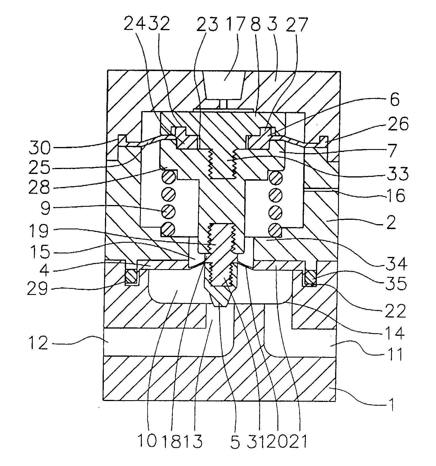
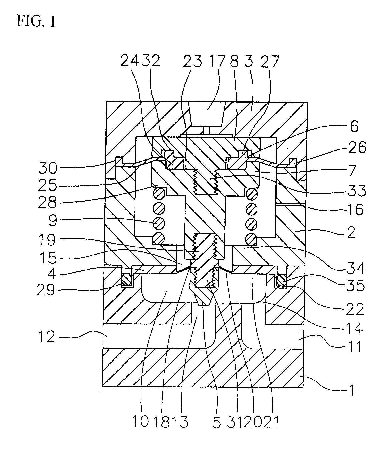
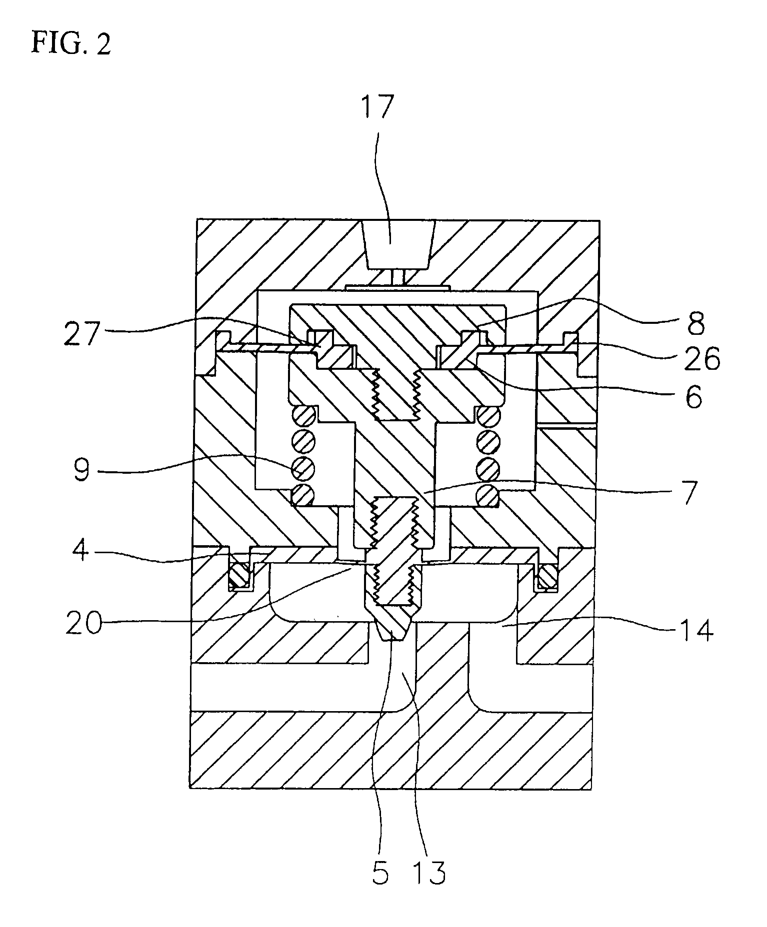
[0024]An embodiment of the present invention is explained below with reference to the drawings. Needless to say, the present invention is not restricted to the description of this embodiment.

[0025]In the drawings, 1 is a polytetrafluoroethylene (PTFE) main body provided with a cylindrical valve chamber 10 in the upper portion thereof, and an inflow channel 11 and outflow channel 12 in the lower portion thereof that respectively communicate with the valve chamber 10. At the valve chamber bottom center, there is an opening 13 that connects with the outflow channel 12, and at the periphery of the opening 13, an opening 14 that connects with the inflow channel 11. The opening 14 has a circular transverse cross-section as shown in FIG. 4, and when the opening 13 is widened to control a larger flow, the opening 14 preferably has a roughly crescent shape formed around the opening 13 provided at the valve chamber bottom center as shown in FIG. 5. The main body 1 has in the upper surface the...


PUM


Abstract

An adjustment valve includes a first diaphragm integrally formed from an attachment section engaged with and fixed to the bottom of a rod, a joining section to which a valve body is fixed, a thin film section radially extending from a shoulder section, a thick wall section continuous with the thin film section, and a seal section provided at the peripheral edge of the thick wall section. The second diaphragm has a central hole, and includes an integrally formed thin film section radially extending from a thick wall section at the center hole, and a seal section is provided at the peripheral edge thereof. A diaphragm hold-down member penetrates the central hole at the shoulder section of the rod, causing the second diaphragm to be sandwiched and fixed. The rod is disposed with play in the through-hole in the bottom of the cylinder, and is supported by a spring engaged between a step section of the cylinder and the bottom surface of the shoulder in a state such that radial movement is prevented.

Description

BACKGROUND OF THE INVENTION[0001]The present invention relates to an adjustment valve used for fluid transport pipes that require flow regulation. More specifically, it relates to an adjustment valve suitable for use mainly in ultrapure water lines and various chemical solution lines in the semiconductor industry.[0002]One example of a conventional fluid control valve is a micro-fluid valve as shown in FIG. 9 (see, for example, Patent Document 1). The constitution will be explained with reference to FIG. 9. There are provided a diaphragm valve 42 in which an annularly formed valve body 37 that comes in contact with and separates from a valve seat 36 is formed integrally with a needle 39 insertable into an orifice 38 provided at the center of the valve seat 36 with thin films constituting an outer film 40 and inner film 41; operation means for causing the valve body 37 to come in contact with and separate from the valve seat 36; and an adjustment screw 43 for adjusting the position o...

Claims


Application Information

Patent Timeline
IPC IPC(8): F16K7/17F16K1/52
CPCF16K1/36F16K1/44F16K41/12F16K31/1262F16K7/123Y10T137/7784F16K1/48F16K7/16F16K7/17
Inventor YAMAMOTO, TAKASHI
Owner ASAHI YUKIZAI KOGYO CO LTD
Why Eureka
Try Eureka