Method of Assembling a Drill Bit with a Jack Element

a drill bit and jack element technology, applied in the field of drill bits, can solve the problems of reducing penetration rate, exceeding the capability of drill bits, and damage to drill bits

Active Publication Date: 2008-05-01
SCHLUMBERGER TECH CORP
View PDF99 Cites 12 Cited by
  • Summary
  • Abstract
  • Description
  • Claims
  • Application Information

AI Technical Summary

Benefits of technology

[0008]In some embodiments the drill bit may be force balanced. The pocket may be brazed and then machined using a mill or lathe to ensure that the jack element is substantially coaxial with the axis of rotation when attached to the pocket. Portions of the at least one cutting element proximate the axis of rotation may be pre-flatted or ground flat in order to accommodate the jack element. The jack element may be brazed, press fit, bonded, welded or threaded into the pocket and protrude from the working face within a range defined by the cutting surface of the at least one cutting element proximate to the axis of rotation Materials suitable for the at least one cutting element or jack element may be selected from the group consisting of di...

Problems solved by technology

Bit whirl in hard formations for example may result in damage to the drill bit and reduce penetration rates.
Further loading too much weight on the drill bit when drilling through a hard formation may exceed the bit's capabilities and also result in damage.
Too often unexpected hard formations are encountered suddenly and damage to the drill bit occurs before the weight on the drill bit may be adjusted.
When a bit fails it reduces productivity...

Method used


Image

  • Method of Assembling a Drill Bit with a Jack Element
  • Method of Assembling a Drill Bit with a Jack Element
  • Method of Assembling a Drill Bit with a Jack Element

Examples


Embodiment Construction

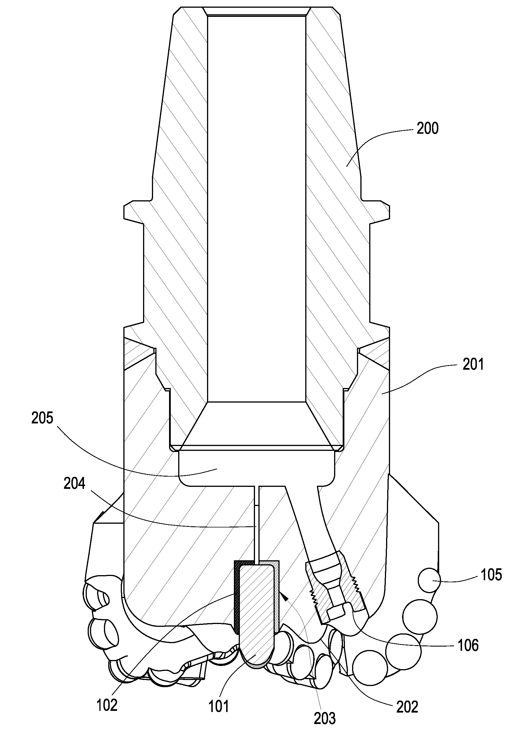
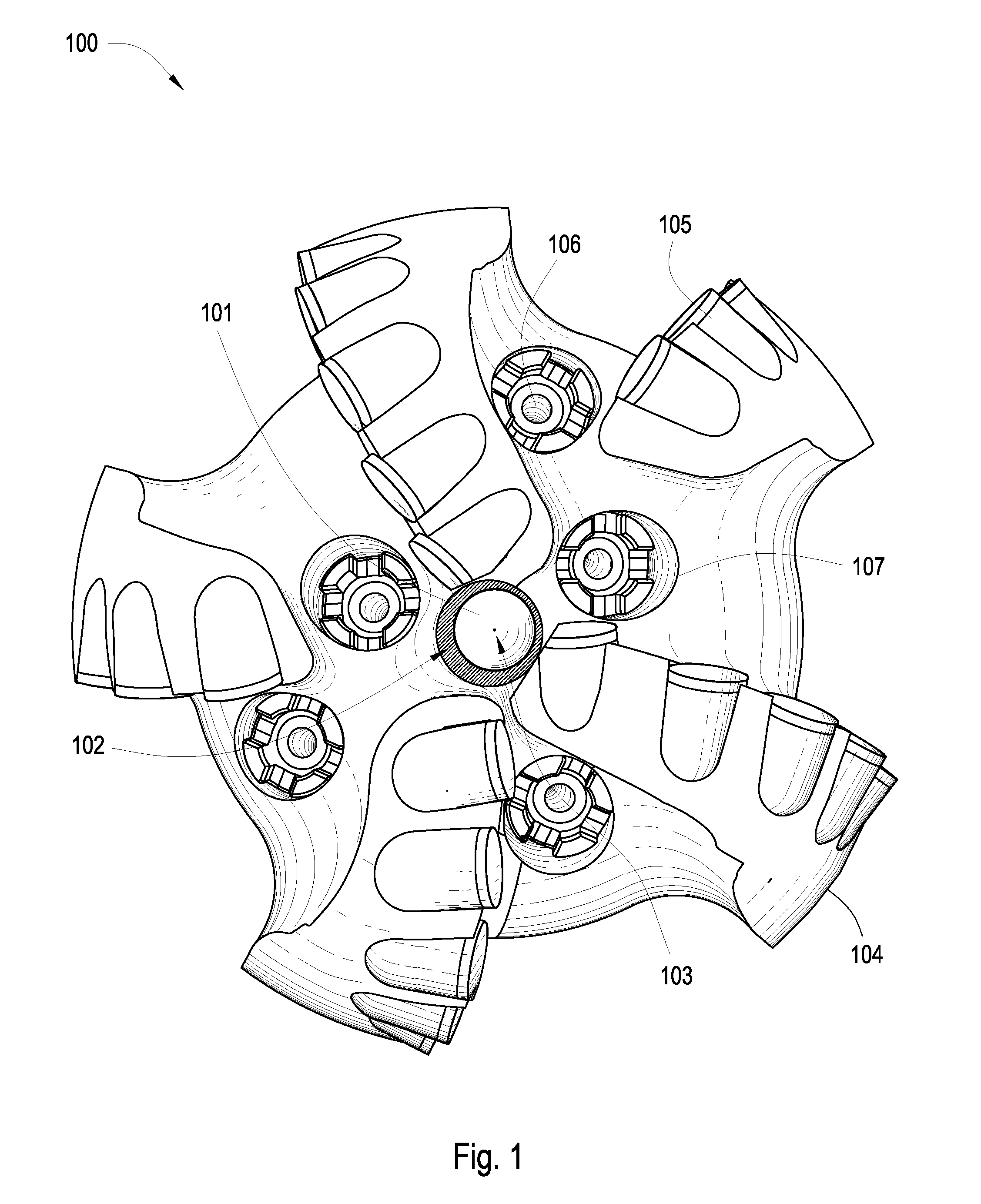
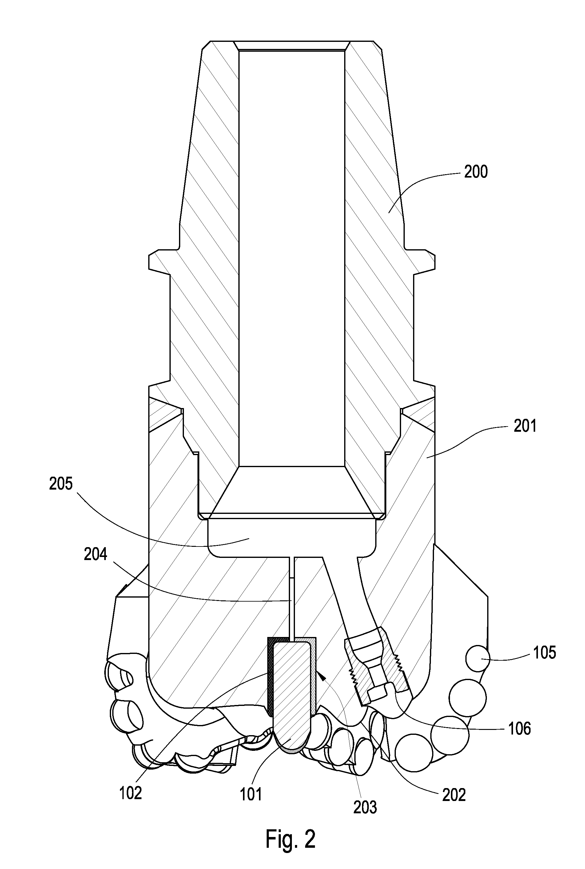
[0019]FIGS. 1 and 2 disclose a drill bit 100 of the present invention The drill bit 100 is formed to comprise a shank 200 which is adapted for connection to a downhole tool string. A bit body 201 is formed and attached to the shank 200 and comprises an end which forms a working face 202. A receptacle 203 is molded into the working face 202 of the drill bit 100 and may be disposed substantially coaxial with the axis 103 of rotation A pocket 102 which may comprise a material selected from the following including aluminum, titanium, steel, mild steel, hardened steel, stainless steel, a metallic alloy or combinations thereof, may be brazed within the receptacle 203 of the working face 202. In some embodiments the receptacle 203 may not be substantially coaxial with the axis 103 of rotation of the drill bit 100. In other embodiments the working face 202 may form a raised buttress that encapsulates the receptacle 203 and protrudes from the center of the working face 202. A channel 204 may...


PUM


Abstract

A method of assembling a drill bit with a bit body intermediate a shank and a working face with a plurality of blades comprised of at least one cutting element. The working face also comprising a jack element disposed within a pocket that may be substantially coaxial with the axis of rotation of the drill bit. The jack element may comprise an abrasion resistant material comprised of a material selected from the following including natural diamond, polycrystalline diamond, boron nitride, tungsten carbide or combinations thereof The jack element may be press fit within a pocket that is brazed within a receptacle of the drill bit such that it is substantially centered coaxial to the rotation of the drill bit.

Description

BACKGROUND OF THE INVENTION[0001]This invention relates to drill bits, specifically drill bit assemblies for use in oil, gas and geothermal drilling. Drill bits are continuously exposed to harsh conditions during drilling operations in the earth's surface. Bit whirl in hard formations for example may result in damage to the drill bit and reduce penetration rates. Further loading too much weight on the drill bit when drilling through a hard formation may exceed the bit's capabilities and also result in damage. Too often unexpected hard formations are encountered suddenly and damage to the drill bit occurs before the weight on the drill bit may be adjusted. When a bit fails it reduces productivity resulting in diminished returns to a point where it may become uneconomical to continue drilling. The cost of the bit is not considered so much as the associated down time required to maintain or replace a worn or expired bit. To replace a bit requires removal of the drill string from the bo...

Claims


Application Information

Patent Timeline
IPC IPC(8): E21B10/00
CPCE21B10/54
Inventor HALL, DAVID R.LEANY, FRANCIS E.FOX, JOEWILDE, TYSON J.
Owner SCHLUMBERGER TECH CORP
Why Eureka
Try Eureka