Electric power steering system

a technology of electric power steering and steering shaft, which is applied in the direction of force/torque/work measurement apparatus, instruments, transportation and packaging, etc., can solve the problems of reducing the detection accuracy of magnetostriction torque sensor b>05/b>, and reducing the detection accuracy of magnetostriction torque sensor, so as to suppress the effect of bending momen

Inactive Publication Date: 2008-05-01
HONDA MOTOR CO LTD
View PDF30 Cites 12 Cited by
  • Summary
  • Abstract
  • Description
  • Claims
  • Application Information

AI Technical Summary

Benefits of technology

[0008]The invention has been made in view of the situations described above, and an object thereof is, in an electric power steering system which includes a magnetostriction torque s

Problems solved by technology

Incidentally, with the electric power steering system described in JP-A-2006-7931 above, since the magnetostriction torque sensor is provided on the pinion shaft of the rack-and-pinion type gear box, there has been a problem inherent therein that the detection accuracy is decreased for reasons below.
Moreover, since the mag

Method used


Image

  • Electric power steering system
  • Electric power steering system
  • Electric power steering system

Examples


first embodiment

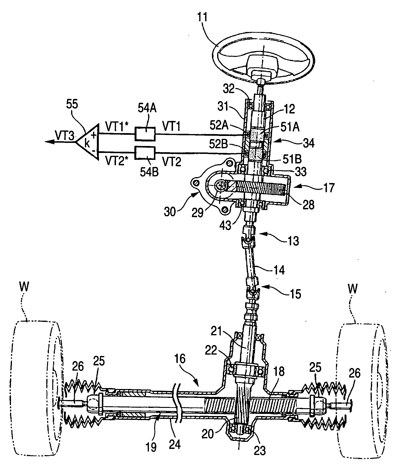
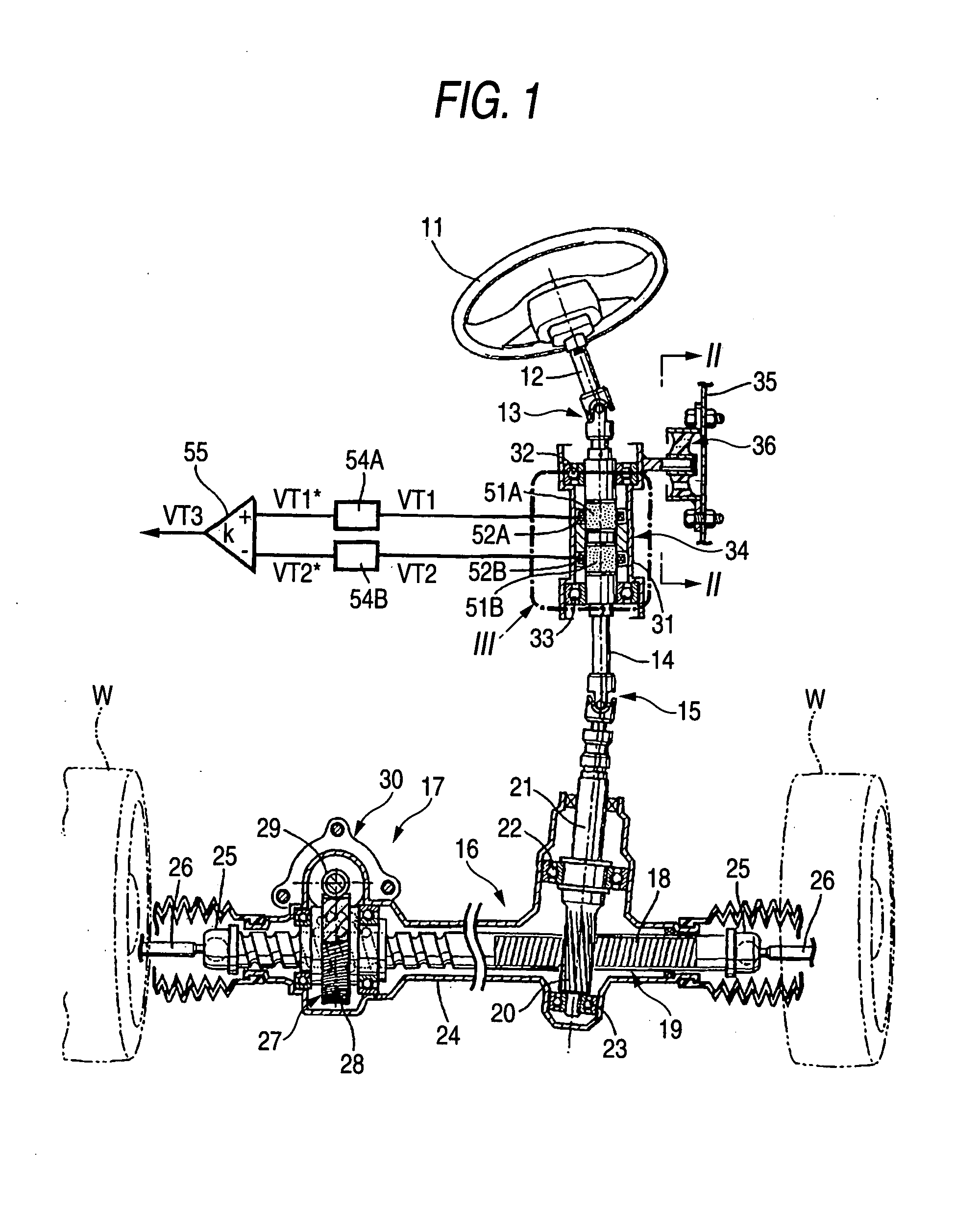
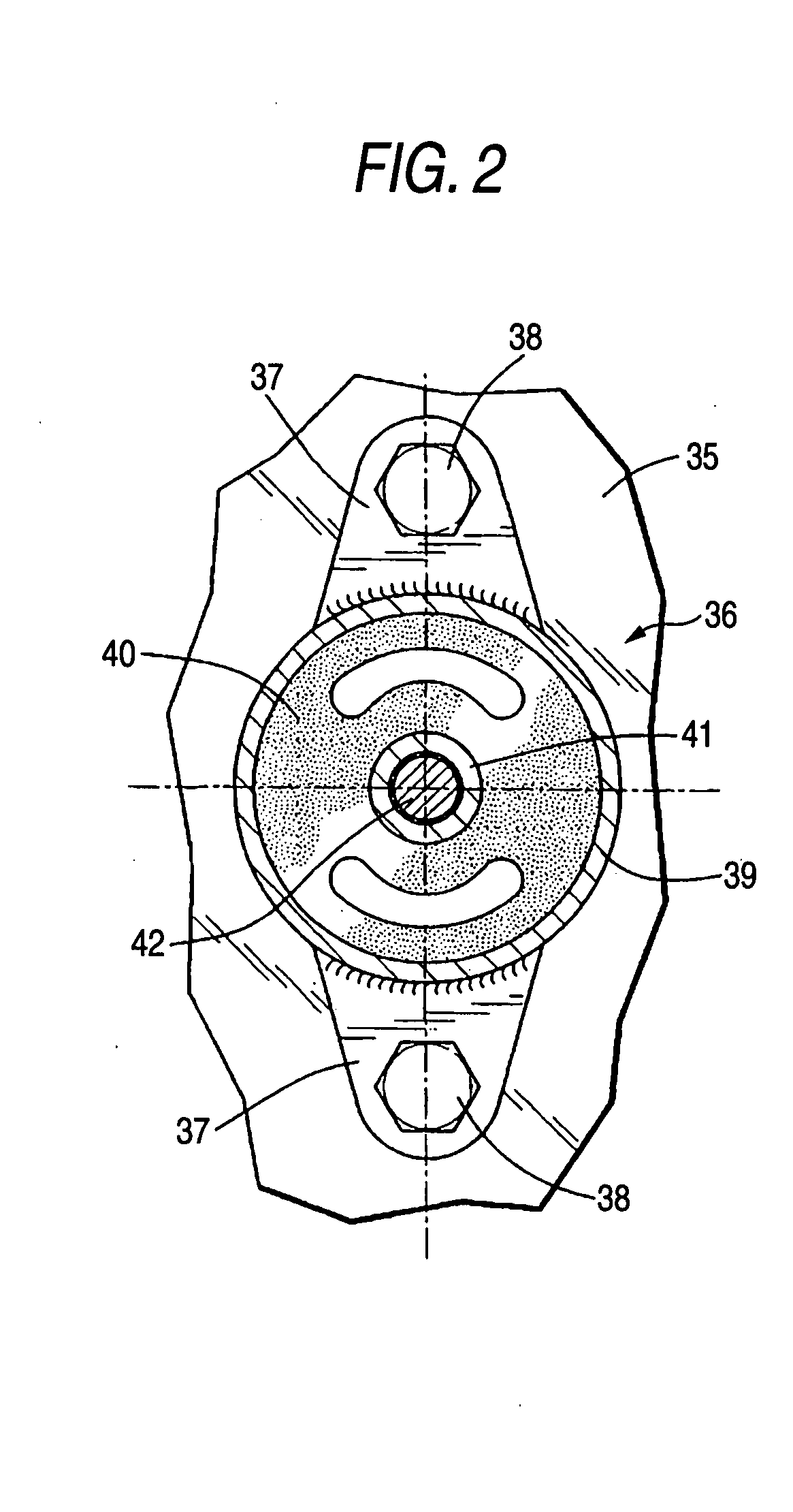
[0040]FIGS. 1 to 4 are such as to show a first embodiment of the invention, of which FIG. 1 is a drawing showing an overall construction of an electric power steering system, FIG. 2 is an enlarged sectional view taken along the line II-II in FIG. 1 and viewed in a direction indicated by arrows at ends of the line, FIG. 3 is an enlarged view of a portion indicated by reference numeral 3 in FIG. 1, and FIG. 4 is a diagram showing changing characteristics of a torque detection signal relative to a steering torque.

[0041]As is shown in FIG. 1, an electric power steering system of a motor vehicle includes an upper steering shaft 12 which is adapted to rotate together with a steering wheel 11, a lower steering shaft 14 which is connected to the upper steering shaft 12 via an upper universal joint 13, a rack-and-pinion steering gear box 16 which is connected to the lower steering shaft 14 via a lower universal joint 15 and a steering actuator 17 provided in the steering gear box 16.

[0042]Th...

second embodiment

[0057]Next, a second embodiment of the invention will be described below based on FIG. 5.

[0058]While in the first embodiment, the magnetostriction torque sensor 34 is provided on the lower steering shaft 14 and the steering actuator 17 is provided in the steering gear box 16, in the second embodiment, both a magnetostriction torque sensor 34 and a steering actuator 17 are provided on an upper steering shaft 12. The upper steering shaft 12 is supported via two ball bearings 32, 33, which are those used in the first embodiment, and an additional ball bearing 43.

[0059]The construction of the magnetostriction torque sensor 34 is the same as that of the magnetostriction torque sensor 34 of the first embodiment. However, a housing therefor is not supported on a vehicle body 35 via an elastic supporting member 36 in a floating fashion but is fixed to the vehicle body 35. The steering actuator 17 is made up of a worm wheel 28 which is fixed to the upper steering shaft 12, a worm 29 which is...


PUM


Abstract

Even in the even that, when a steering torque is applied to a steering wheel 11 of an electric power steering system, a pinion shaft 21 of a rack-and-pinion steering gear box 16 is curved by a bending moment generated by a reaction force which a pinion 20 receives from a rack 18, since a steering shaft 14 on which a magnetostriction torque sensor 34 is provided is connected to the pinion shaft 21 via a universal joint 15, the transmission of the bending moment to the steering shaft 14 is made difficult to occur. As a result, the effect imposed by the bending moment on the detection accuracy of the magnetostriction torque sensor 34 provided on the steering shaft 14 can be suppressed to a minimum level.

Description

BACKGROUND OF THE INVENTION[0001]1. Field of the Invention[0002]The present invention relates to an electric power steering system in which a steering wheel and a rack-and-pinion type gear box are connected together by a steering shaft, a steering torque that is inputted into the steering wheel is detected by a magnetostriction torque sensor, and a steering actuator is driven according to a steering torque so detected so as to assist the driver to perform a steering operation.[0003]2. Description of Related Art[0004]A technique is known in JP-A-2006-7931 in which a steering torque that is inputted into a steering wheel is detected by a magnetostriction torque sensor, so as to calculate a target torque that is to be generated in a motor of an electric power steering system based on the steering torque so detected. The magnetostriction torque sensor includes a magnetostriction membrane which is formed on an outer circumference of a pinion shaft in such a manner as to have a magnetic a...

Claims


Application Information

Patent Timeline
IPC IPC(8): B62D5/04G01L3/00
CPCB62D1/16G01L5/221G01L3/102B62D6/10
Inventor SHIMIZU, YASUOWATANABE, KATSUJIYONEDA, ATSUHIKO
Owner HONDA MOTOR CO LTD
Why Eureka
Try Eureka