Deformation sensor

a technology of deformation sensor and elastomer, which is applied in the direction of instruments, pedestrian/occupant safety arrangements, force/torque/work measurement apparatus, etc., can solve the problems of large shock which requires the operation of the occupant protection device, and achieve excellent compatibility between the conductive filler and the elastomer

Inactive Publication Date: 2008-05-01
SUMITOMO RIKO CO LTD
View PDF14 Cites 35 Cited by
  • Summary
  • Abstract
  • Description
  • Claims
  • Application Information

AI Technical Summary

Benefits of technology

[0055](22) Preferably, in the construction of the above (12), it is constructed that the above-mentioned elastomer includes one rubber selected from the group consisting of silicone rubber, ethylene-propylene copolymer rubber, natural rubber, styrene-butadiene copolymer rubber, acrylonitrile-butadiene copolymer rubber and acrylic rubber. According to the present construction, the compatibility between the conductive fillers and the elastomer is excellent. On this account, the conductive fillers are easy to exist in a primary particle state.

Problems solved by technology

In other words, when the transmission member is deformed, it is conceivable that a big shock which requires an operation of the occupant protection device is applied.

Method used


Image

  • Deformation sensor
  • Deformation sensor
  • Deformation sensor

Examples


first preferred embodiment

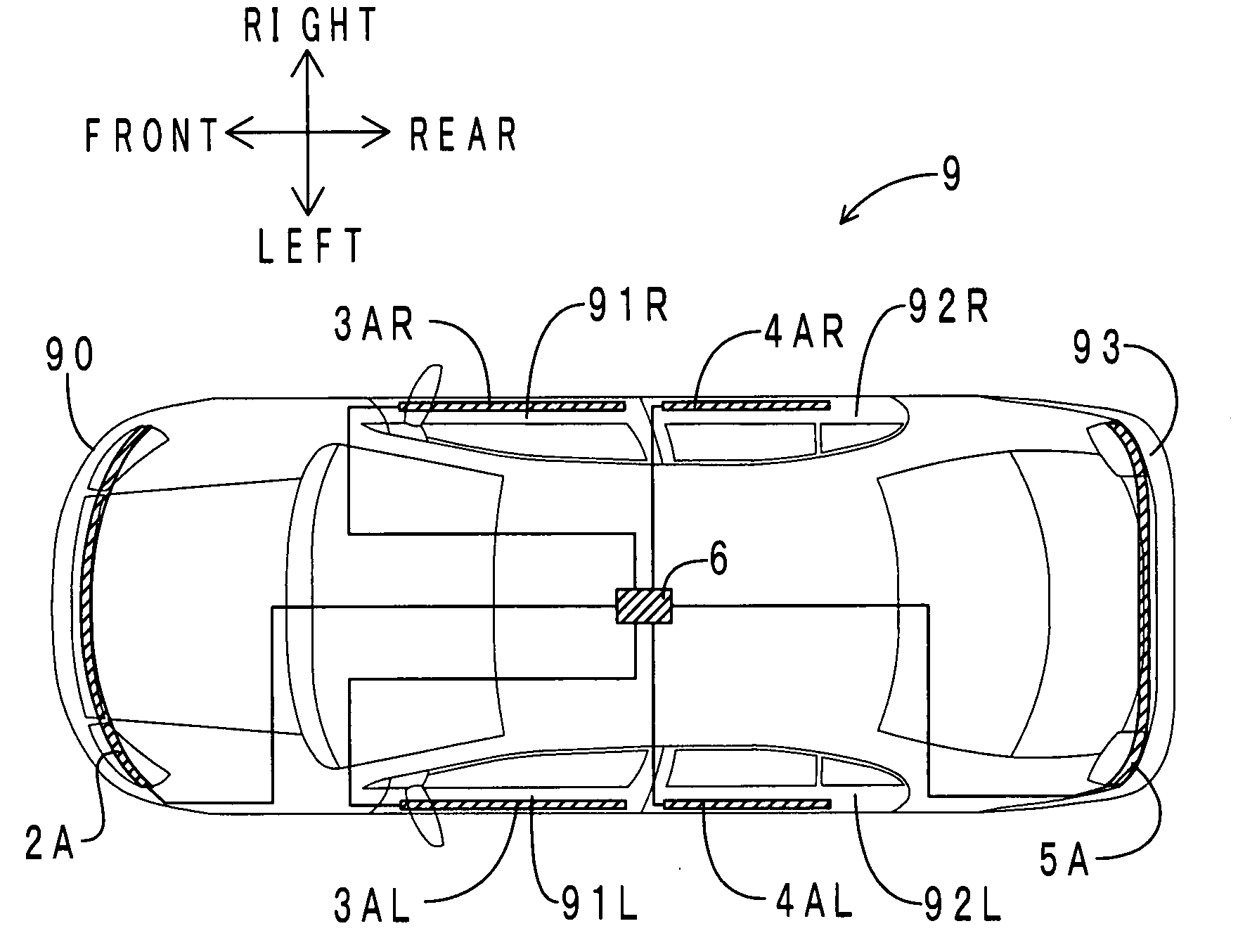
[0097]First, an arrangement of the deformation sensor in this preferred embodiment will be explained. FIG. 4(a) is a transmitted upper surface view of a vehicle in which the deformation sensor is arranged. FIG. 4(b) is a transmitted lateral view of the vehicle. By the way, in Figures following to FIG. 4, an orientation is defined on the basis of a forward direction of a vehicle 9.

[0098]As shown in FIG. 4, as for the vehicle 9, a front bumper sensor unit 2A is built in a front bumper 90, a left front door sensor unit 3AL is built in a left front door 91L, a left rear door sensor unit 4AL is built in a left rear door 92L, a right front door sensor unit 3AR is built in a right front door 91R, a right rear door sensor unit 4AR is built in a right rear door 92R, and a rear bumper sensor unit 5A is built in a rear bumper 93, respectively (in FIG. 4, as a matter of convenience for explanation, these sensor units are shown as hatching). Furthermore, under an approximately central floor of t...

second preferred embodiment

[0161]The difference between the first preferred embodiment and this preferred embodiment is that a bridge circuit and an amplifier are shared with respect to all deformation sensors. Therefore, here, only the difference will be explained.

[0162]FIG. 15 is a block diagram of an occupant protection system of this preferred embodiment. By the way, portions corresponding to FIG. 12 are indicated as the same symbols. As shown in FIG. 15, a bridge circuit 62 and an amplifier 63 are arranged in an occupant protection ECU 6.

[0163]FIG. 16 is a circuit diagram of the bridge circuit 62. As shown in FIG. 16, the bridge circuit 62 is connected with each of a front bumper sensor 20, a left front door sensor 30L, a left rear door sensor 40L, a right front door sensor 30R, a right rear door sensor 40R and a rear bumper sensor 50. These sensors are all included in the first deformation sensor of the present invention. Each sensor constitutes a Wheatstone bridge circuit together with resistances R10 ...

third preferred embodiment

[0176]First, an arrangement of the deformation sensor in this preferred embodiment will be explained. FIG. 17 (a) is a transmitted upper surface view of a vehicle in which the deformation sensor is arranged. FIG. 17 (b) is a transmitted lateral view of the vehicle. By the way, portions corresponding to FIG. 4 are indicated as the same symbols.

[0177]As shown in FIG. 17, as for the vehicle 9, a front bumper sensor unit 2B is built in a front bumper 90, a left front door sensor unit 3BL is built in a left front door 91L, a left rear door sensor unit 4BL is built in a left rear door 92L, a right front door sensor unit 3BR is built in a right front door 91R, a right rear door sensor unit 4BR is built in a right rear door 92R, and a rear bumper sensor unit 5B is built in a rear bumper 93, respectively (in FIG. 17, as a matter of convenience for explanation, these sensor units are shown as hatching). Furthermore, under an approximately central floor of the vehicle 9, an occupant protection...


PUM


Abstract

A first deformation sensor is arranged in a shock transmission member which is built in a vehicle and which constitutes a transmission path of a shock applied from the outside. A second deformation sensor is arranged in an exterior member which is exposed to the outside of a vehicle. Each of the first and second deformation sensors comprises a main body of sensor which has an elastomer and spherical conductive fillers blended in the elastomer in an approximately single particle state and with a high filling rate, and in which an electric resistance increases as an elastic deformation increases, and an electrode which is connected with the main body of sensor and is able to output the electric resistance.

Description

INCORPORATION BY REFERENCE[0001]This application is based on and claims priority under 35 U.S.C. 119 with respect to Japanese Patent Application Nos. 2006-290100 and 2006-290146, both of which were filed on Oct. 25, 2006, and the entire content of which is incorporated herein by reference.BACKGROUND OF THE INVENTION[0002]1. Field of the Invention[0003]The present invention relates to a deformation sensor which is mounted on a vehicle and which can detect a collision and so on of a vehicle.[0004]2. Description of the Related Art[0005]An occupant protection system for protecting an occupant at the time of collision is equipped with automobiles. The occupant protection system comprises a sensor for detecting a shock, an occupant protection ECU (an electronic control unit) for judging whether or not a collision occurs based on a signal from the sensor and an occupant protection device such as an air bag and so on. Here, the sensor for detecting the shock includes, for example, an accele...

Claims


Application Information

Patent Timeline
Patent Type & Authority Applications(United States)
IPC IPC(8): B60R21/16
CPCB60R19/483B60R21/0136G01L5/0052G01L1/2281G01L1/20
Inventor HAYAKAWA, TOMONORISAITOU, YUUKIHASHIMOTO, KAZUNOBUKATO, RENTARO
Owner SUMITOMO RIKO CO LTD
Why Eureka
Try Eureka