Power supply system and method on board an aircraft

a technology for power supply systems and aircraft, applied in the direction of dc source parallel operation, electric devices, transportation and packaging, etc., can solve the problems of specific equipment that is costly and difficult to replace, and the load ci to which it is dedicated cannot be powered

Inactive Publication Date: 2008-05-01
AIRBUS OPERATIONS (SAS)
View PDF11 Cites 49 Cited by
  • Summary
  • Abstract
  • Description
  • Claims
  • Application Information

AI Technical Summary

Problems solved by technology

The following disadvantages result: During a failure of a power module CVSi, the load Ci to which it is dedicated ca

Method used


Image

  • Power supply system and method on board an aircraft
  • Power supply system and method on board an aircraft
  • Power supply system and method on board an aircraft

Examples


case b

ng the Engine

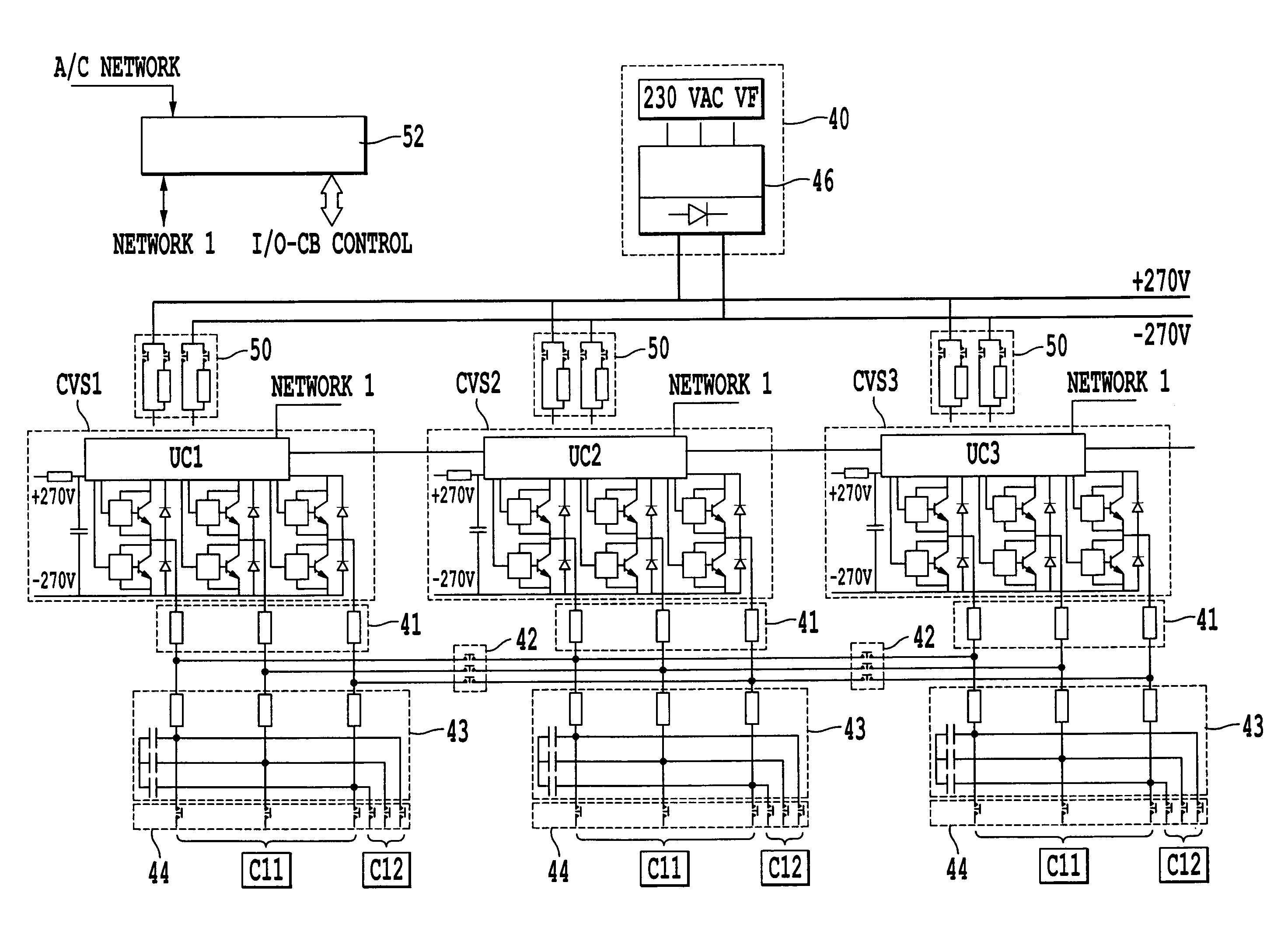
[0122] The power module CVS1 operates as an inverter and the piloting used is devoted to starting the engines of the aeroplane (DM1).

[0123] The power module CVS2 operates as an inverter and the piloting used permits the generation of a 115 volts A.C. 400 Hz network.

Case C: Air Conditioning Unit In Downgraded Mode

[0124] The opposed air conditioning unit ECS has broken down and the remaining air conditioning unit must provide 150% of its nominal power. To avoid over sizing the power module CVS1, the power module CVS2 is used in parallel with the power module CVS1 to permit this extra power to be transmitted. The two power modules CVS1 and CVS2 are connected in parallel by means of inductances and a contactor. The commands of these two power modules may be synchronous or shifted by π. The loads which were on the 115 volts A.C. network have been either redistributed to the three other 115 volts A.C. networks, or abandoned according to their degree of criticality.

Case D:...


PUM


Abstract

The invention relates to a system and a power supply method, on board an aircraft. The power supply system of an aircraft comprises several generators powering with 230 volts A.C. several distinct electrical cores, wherein the various loads of the aeroplane are connected to each of these cores, in which each core comprises:
    • an input driver (40),
    • several identical power modules (CVS1 . . . CVSn),
    • means of placing in parallel several power modules comprising interconnection inductances (41) between power modules, and a switching matrix (42, 44) comprising a set of contactors,
    • means (52) of piloting the contactors of the switching matrix (42, 44), so as to reconfigure all of these contactors in the case of failure of a power module,
    • several output filters (43),
    • contactors (44) of the switching matrix (42, 44) that may each be connected to at one load (Cij).

Description

TECHNICAL FIELD [0001] The present invention relates to a power supply system and a method, on board an aircraft. [0002] In the following description, for reasons of simplification, by way of example, an aeroplane type of aircraft will be considered. STATE OF THE PRIOR ART [0003] In future aeroplanes, the increase in part of electrical energy used will lead to an increase in the number of generators and electrical cores (or electrical housings). One example of the architecture of electrical generation and distribution is thus provided in FIG. 1. Four generators are shown GEN 1.1, GEN 1.2, GEN 2.1 and GEN 2.2 supplying with an alternating current (for example 230 VAC) four distinct electrical cores 10, 11, 12 and 13 for a first and a second side 14 and 15 of the aeroplane. The various electrical consumers (loads) of the aeroplane are connected to each of these cores. By way of example, the loads 20, 21, 22 and 23 which appear on this FIG. 1 are typical of a “more electrical” aeroplan...

Claims


Application Information

Patent Timeline
IPC IPC(8): B60L1/00H02J1/00
CPCH02J1/10H02J5/00H02J4/00H02J3/38H02J2310/44
Inventor LANGLOIS, OLIVIERPRISSE, LUCIENFOCH, ETIENNEALEJO, DOMINIQUE
Owner AIRBUS OPERATIONS (SAS)
Why Eureka
Try Eureka