

Thermal Print Head
a print head and thermal technology, applied in the field of thermal print heads, can solve the problems of insufficient current supply to the heating portions, reduced current flow through the electrodes,
- Summary
- Abstract
- Description
- Claims
- Application Information
AI Technical Summary
Benefits of technology
Problems solved by technology
Method used
Image

Examples
first embodiment
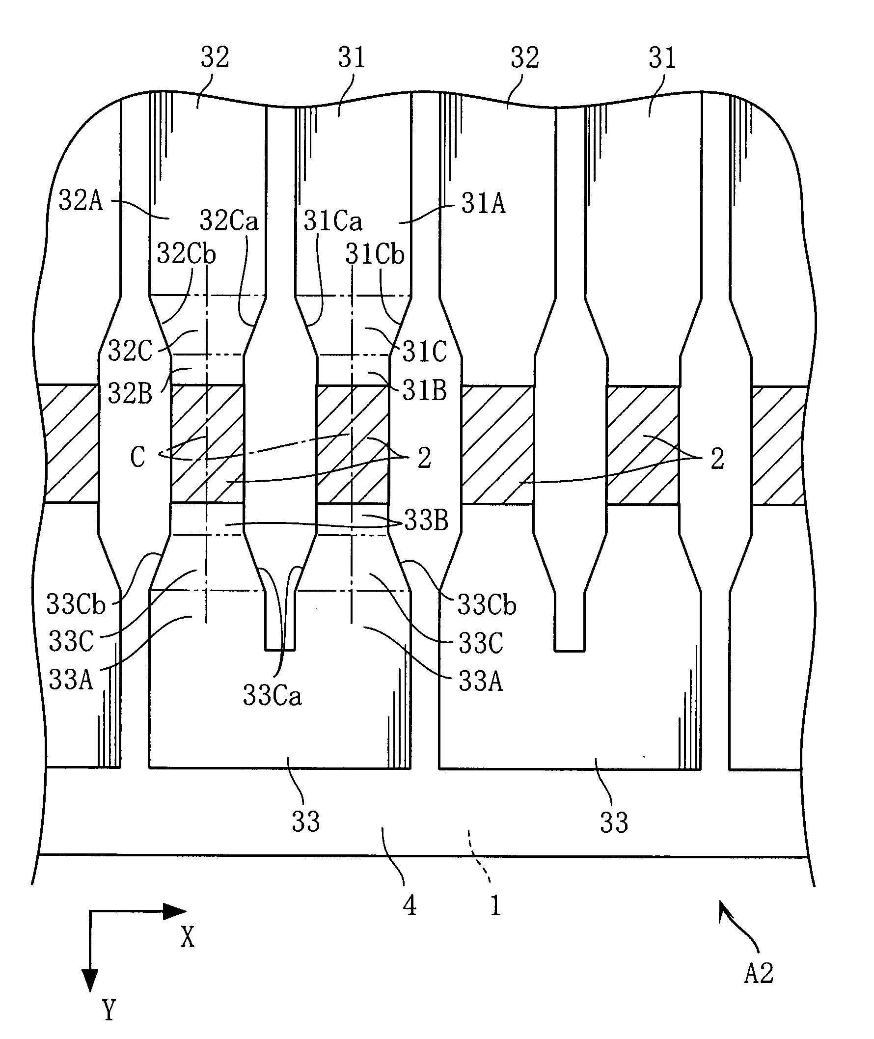
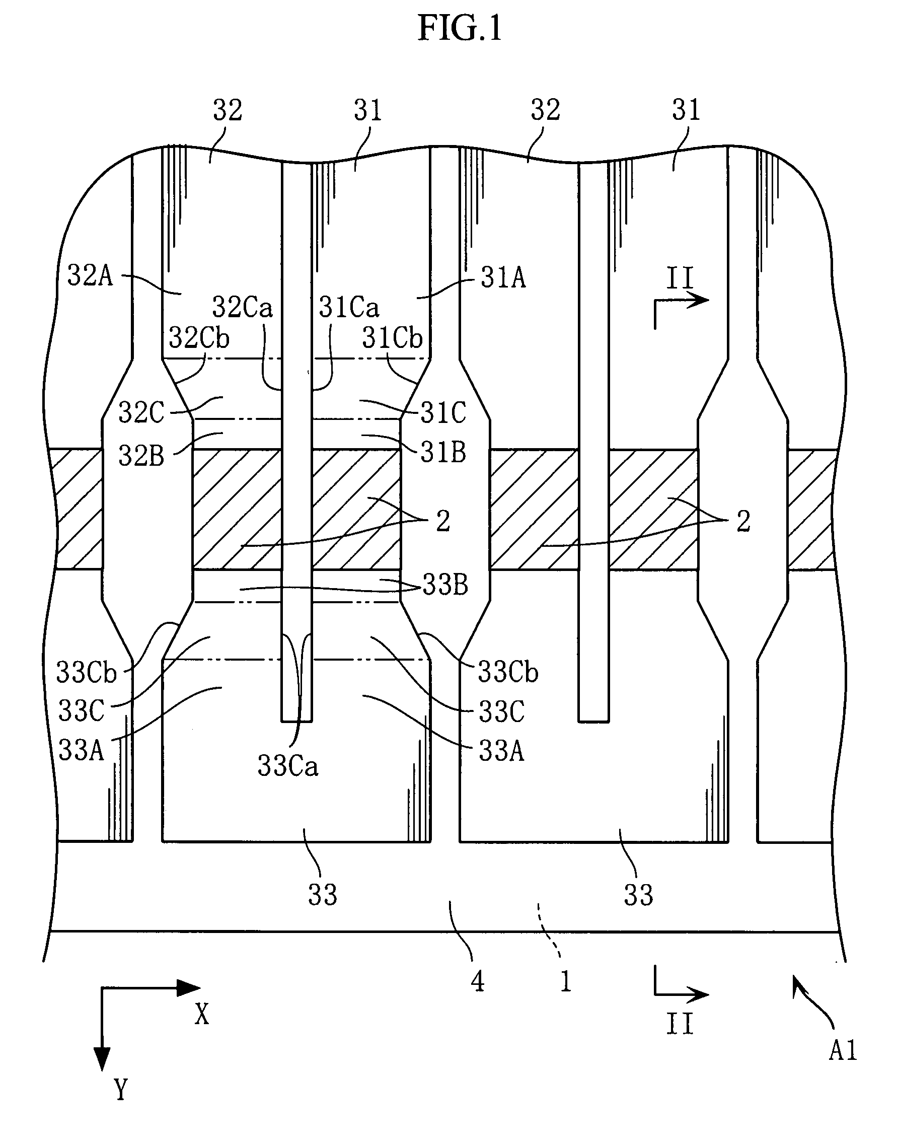
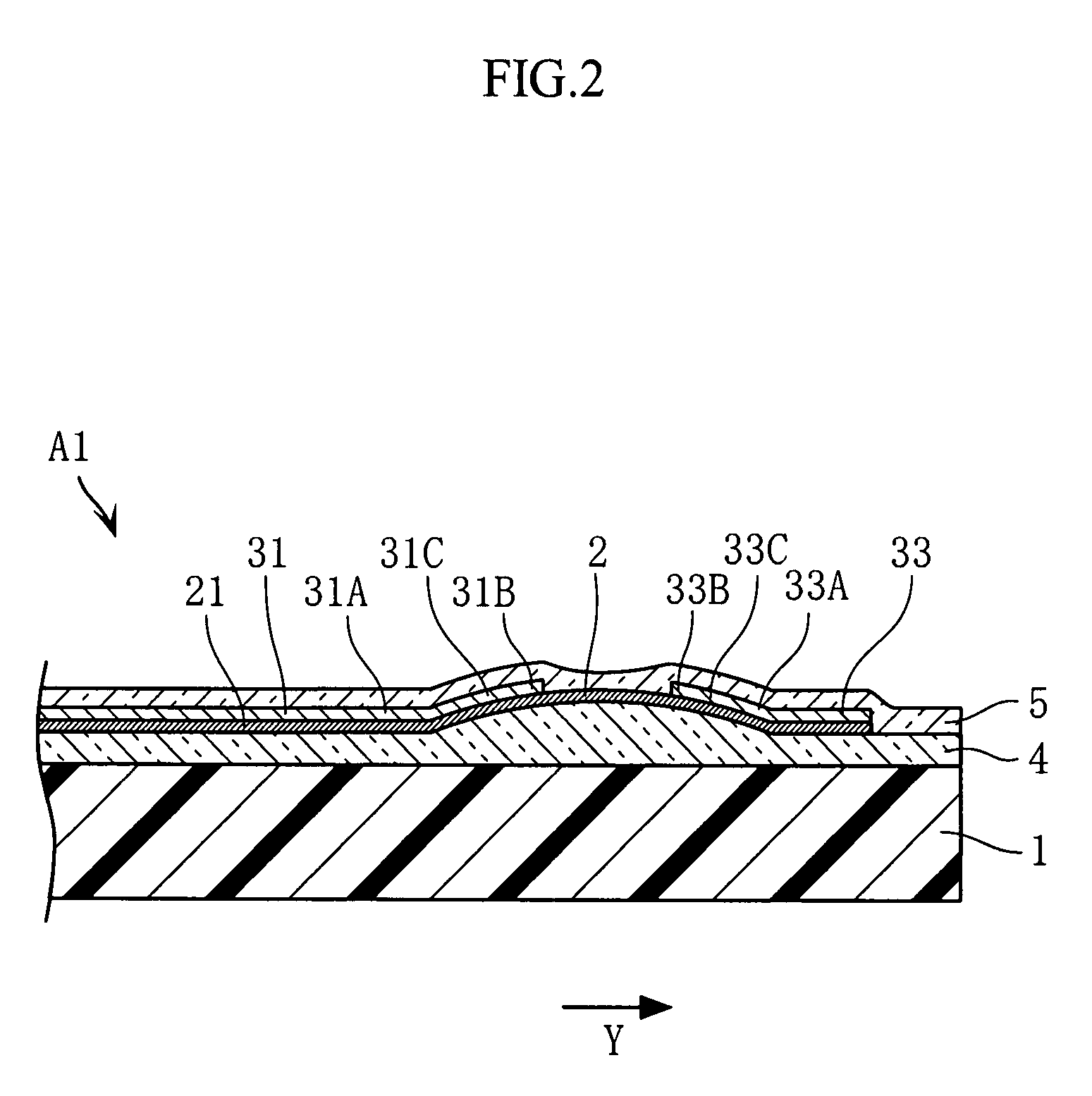
[0020]FIGS. 1 and 2 show a thermal printhead according to the present invention. The thermal printhead Al includes a substrate 1, a plurality of heating portions 2, a plurality of individual electrodes 31, 32, a plurality of intermediate electrodes 33, a glaze layer 4 and a protective layer 5 (not shown in FIG. 1).
[0021]The substrate 1 is in the form of a flat rectangular plate elongated in a primary scanning direction X in a plan view and may be made of an insulating material such as alumina ceramic material.
[0022]As shown in FIG. 1, the heating portions 2 are aligned in the primary scanning direction X. The heating portions 2 may be made of a TaSiO2 sputtered film or other metal films. As will be described later, a pair of heating portions 2 which are adjacent to each other in the primary scanning direction X form a single print dot.
[0023]The individual electrodes 31, 32 and the intermediate electrodes 33 are made of a metal (such as aluminum or gold) having a lower electrical res...
second embodiment
[0036] each of the heating portions 2 and the relevant wide portion 31A, 32A, 33A are arranged on the same line. The heating portion 2 and the wide. portion 31A, 32A, 33A are electrically connected to each other via the axisymmetric tapered portion 31C, 32C, 33C. With this arrangement, current flows uniformly in the secondary scanning direction Y through the wide portions 31A, 32A, 33A having a relatively large width and the heating portions 2 having a relatively small width, and the direction of the current is not disordered locally. As a result, non-uniform heat generation distribution in the heating portions 2 can be avoided, so that print dots are more reliably prevented from being blurred or distorted.
[0037]Further, according to the second embodiment, a relatively large distance can be secured between the paired heating portions 2. When the distance between paired heating portions 2 is large, the heating portions when energized are prevented from heating each other to reach an ...
fourth embodiment
[0039]When the thermal printhead has an electrode pattern which turns around at the intermediate electrodes 33 like the thermal printhead A1-A3, the heating portions 2 can be arranged at a position which is offset toward an edge of the substrate 1. This structure is suitable for pressing the heating portions 2 against e.g. thermal paper with high pressure to perform high-definition and high-speed printing. However, like the thermal printhead A4 shown in FIG. 5 (fourth embodiment of the present invention), the structure including a comb-teeth shaped common electrode 34 maybe employed. With this structure again, by the provision of the tapered portions 31C and 34C, printing can be performed, similarly to the foregoing embodiments, with high definition and high speed.
[0040]The thermal printhead according to the present invention is not limited to the foregoing embodiments. The specific structure of each part of the thermal printhead according to the present invention may be varied in d...
PUM
 Abstract
Description
Claims
Application Information