Illumination apparatus and projection display device

a technology of projection display and projection apparatus, which is applied in the direction of lighting and heating apparatus, instruments, optical elements, etc., can solve the problems of increasing the manufacturing cost of the projection display apparatus as a whole, and achieve the reduction of the designation load accompanying the application of the new type, the effect of suppressing the increase in the manufacturing cost of the entire apparatus

Active Publication Date: 2008-05-01
SANYO ELECTRIC CO LTD
View PDF1 Cites 19 Cited by
  • Summary
  • Abstract
  • Description
  • Claims
  • Application Information

AI Technical Summary

Benefits of technology

[0013]According to the above aspect, the polarization adjustment element transmits the superimposed component light without adjusting the polarization and transmits the fourth color component light with adjusting the polarization. The fourth color component light and the superimposed component light emitted from the polarization adjustment element, enter a light valve corresponding to the superimposed component light. Namely, the fourth color component light is superimposed on the superimposed component light so as to be supplied to a color combiner. Accordingly, the number of types of light to enter the color combiner is three even when the fourth color component light is utilized in addition to the red component light, the green component light and the blue component light. As a result, there is no need to change design of a projection mean and it i

Problems solved by technology

As a result, a projection mean used in a projection display apparatus using light of three colors cannot be used for the one u

Method used


Image

  • Illumination apparatus and projection display device
  • Illumination apparatus and projection display device
  • Illumination apparatus and projection display device

Examples


first embodiment

(Outline of a Projection Display Device)

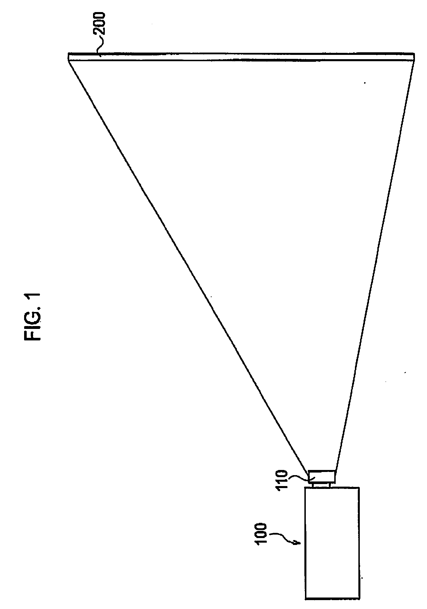
[0038]An outline of a projection display device according to a first embodiment of the present invention will be described below by referring to the drawings. FIG. 1 is a view schematically showing a projection display device 100 according to the first embodiment.

[0039]As shown in FIG. 1, the projection display device 100 has a projection lens unit 110 and projects image light enlarged by the projection lens unit 110 onto a screen 200. As will be described later, the projection display device 100 uses yellow component light as fourth color component light in addition to red component light, green component light, and blue component light.

(Schematic Configuration of a Lighting Unit)

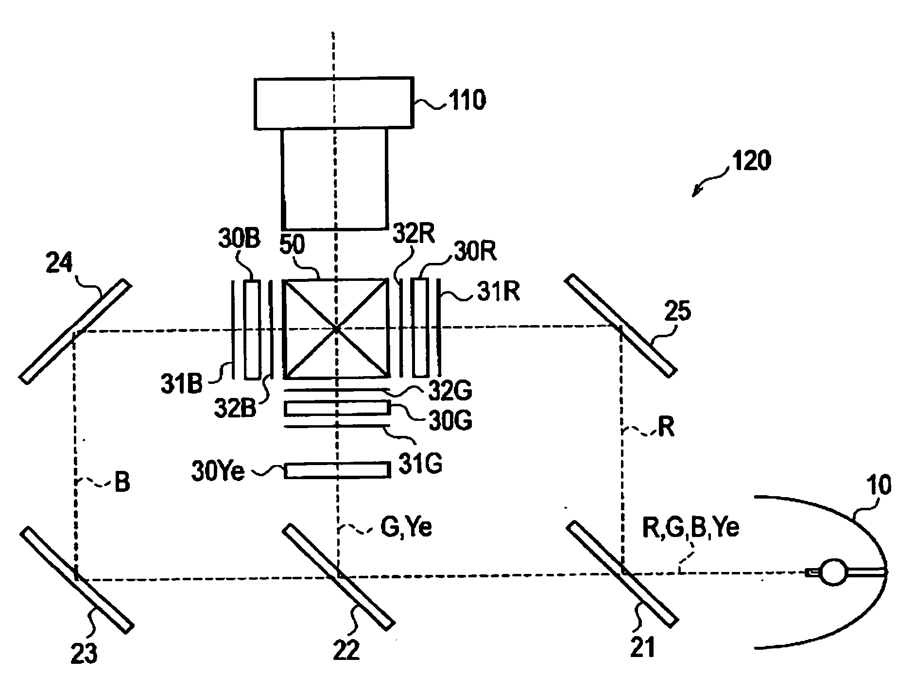
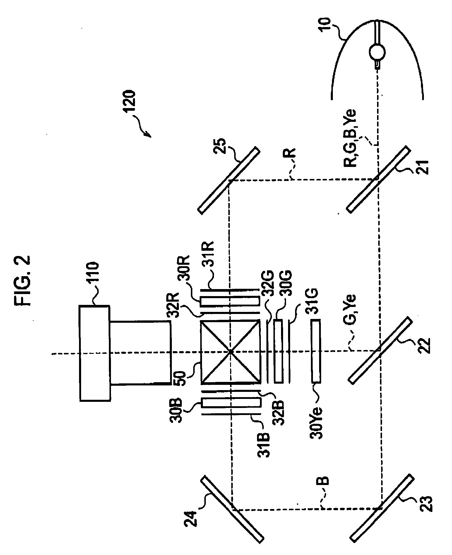
[0040]A schematic configuration of a lighting unit according to the first embodiment will be described below by referring to the drawing. FIG. 2 is a view schematically showing a configuration of a lighting unit 120 according to the first embodiment. Note that in FIG...

second embodiment

[0074]A second embodiment of the present invention will be described below by referring to the drawings. In the following, the description will be mainly given to denote differences between the above-mentioned first embodiment and the second embodiment.

[0075]Specifically, it is not particularly mentioned in the above-mentioned first embodiment, but in the second embodiment, a rotation amount of yellow component light rotated by a polarization adjustment element 30Ye is controlled according to red input signal, green input signal, and blue input signal.

[0076]In addition, in the above-mentioned first embodiment, the polarization adjustment element 30Ye is an element configured to selectively switch whether a polarization direction of yellow component light is not rotated or a polarization direction of yellow component light is rotated at 90°. In contrast, in the second embodiment, a polarization direction of yellow component light is controlled in a range of 0 to 90°, by adjusting the...

third embodiment

[0090]A third embodiment of the present invention will be described below by referring to the drawings. In the following, the description will be mainly given to differences between the above-mentioned first embodiment and the third embodiment.

[0091]Specifically, in the above-mentioned first embodiment, a transmission type crystal panel is used as a light valve, but in the third embodiment, a reflection-type liquid crystal panel (LOCS: Liquid Crystal On Silicon) is used as a light valve.

(Configuration of a Lighting Unit)

[0092]A schematic configuration of a lighting unit according to the third embodiment will be given below by referring to the drawing. FIG. 8 is a view showing a schematic configuration of a lighting unit 120 according to the third embodiment. Note that in FIG. 8, similar reference numerals will be given to denote components similar to those of the first embodiment.

[0093]As shown in FIG. 8, the lighting unit 120 has a light source 10, a plurality of liquid crystal pan...


PUM


Abstract

An illumination apparatus includes a red light valve, a green light valve, a blue light valve, a polarization adjustment element, and a color combiner. The polarization adjustment element adjusts polarization of fourth color component light. The color combiner combines light emitted from the red light valve, the green light valve and the blue light valve. Superimposed component light which is any one of a red component light, a green component light and a blue component light enters the polarization adjustment element together with a fourth color component light. The polarization adjustment element transmits the superimposed component light without adjusting the polarization, and transmits the fourth color component light with adjusting the polarization. The superimposed component light and the fourth color component light emitted from the polarization adjustment element enter a specific light valve corresponding to the superimposed component light, among the red light valve, the green light valve and the blue light valve.

Description

CROSS REFERENCE TO ELATED APPLICATIONS[0001]This application is based upon and claims the benefit of priority from prior Japanese Patent Application No. 2006-296282, filed on Oct. 31, 2006; and Japanese Patent Application No. 2007-249576, filed on Sep. 26, 2007; the entire contents of which are incorporated herein by reference.BACKGROUND OF THE INVENTION[0002]1. Field of the Invention[0003]The present invention relates to an illumination apparatus and a projection display device, which utilize fourth color component light in addition to red component light, green component light, and blue component light.[0004]2. Description of the Related Art[0005]Conventionally, a projection display device has been known, which provided with light valves corresponding to three colors, a cross dichroic cube that combines lights emitted from the three light valves, and a projection mean that projects a light combined by the cross dichroic cube.[0006]Herein, the cross dichroic cube has three light in...

Claims


Application Information

Patent Timeline
IPC IPC(8): G03B21/20F21V9/14
CPCG02B27/283G03B21/14H04N9/3167G03B33/12G03B33/04G03B21/2073G03B21/208
Inventor KANAYAMA, HIDEYUKIMAEDA, MAKOTOIKEDA, TAKASHIMASHITANI, KEN
Owner SANYO ELECTRIC CO LTD
Why Eureka
Try Eureka