Scroll fluid machine

a fluid machine and rotating technology, applied in the direction of machines/engines, liquid fuel engines, rotary piston liquid engines, etc., can solve the problems of reducing sealing performance, increasing the overall size of the compressor, and affecting the operation of the machine, so as to reduce the size, increase the pressure-receiving area, and provide the effect of back-pressur

Active Publication Date: 2008-05-01
HITACHI LTD
View PDF4 Cites 14 Cited by
  • Summary
  • Abstract
  • Description
  • Claims
  • Application Information

AI Technical Summary

Benefits of technology

[0008]Accordingly, an object of the present invention is to provide a scroll fluid machine capable of readily providing a back-pressure chamber having an increased pressure-receiving area and yet capable of being reduced in size.

Problems solved by technology

When compressed air is produced, the pressure of compressed air may apply an excessive thrust load to the orbiting scroll member in the direction of the rotating shaft.
Thus, the overall size of the compressor tends to increase.
Consequently, the sealing performance degrades even when only one of the two seal members has become worn.
Thus, reliability is likely to decrease.
This causes the compressor to increase in size diametrically.

Method used


Image

  • Scroll fluid machine
  • Scroll fluid machine
  • Scroll fluid machine

Examples


Embodiment Construction

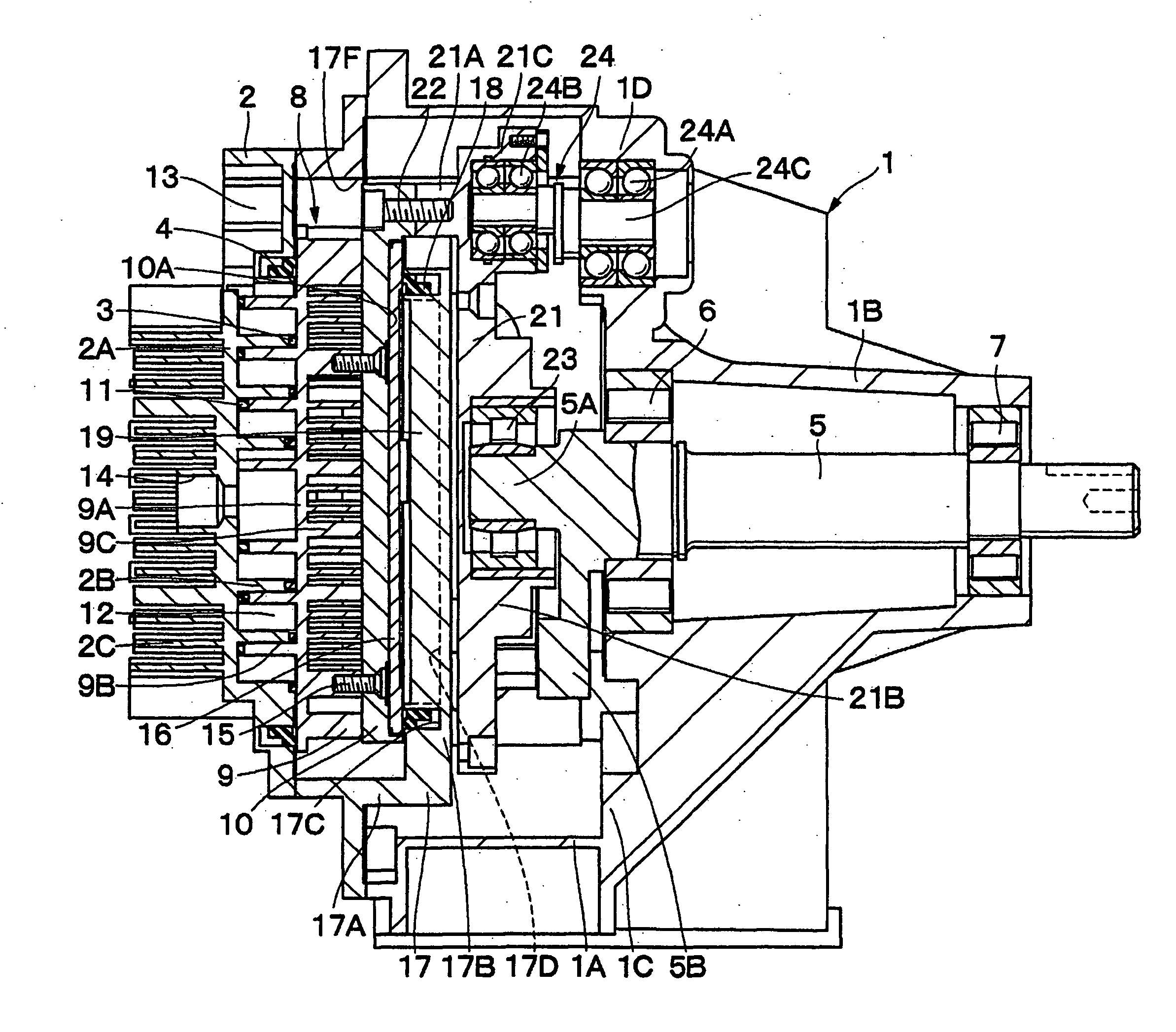
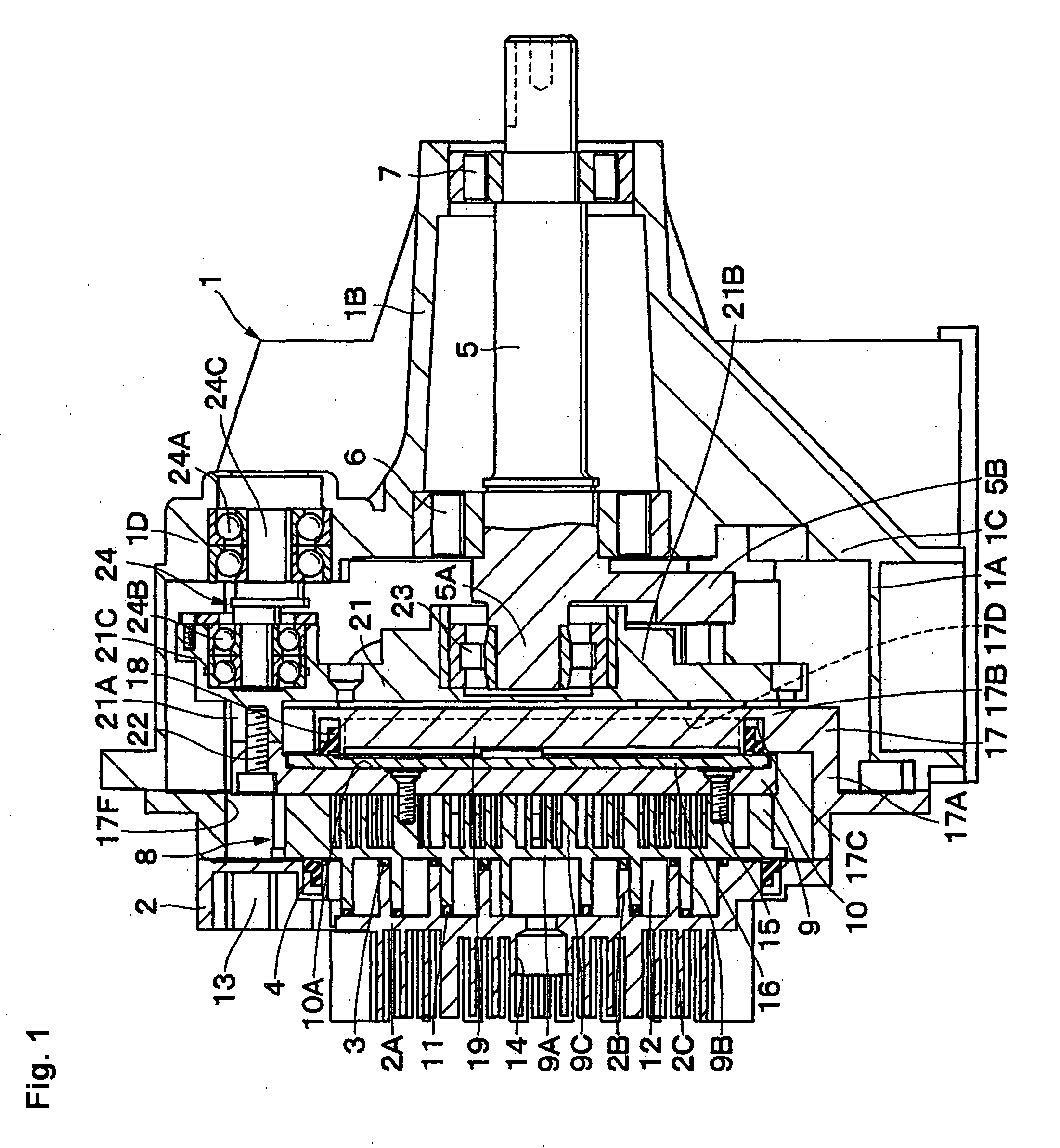
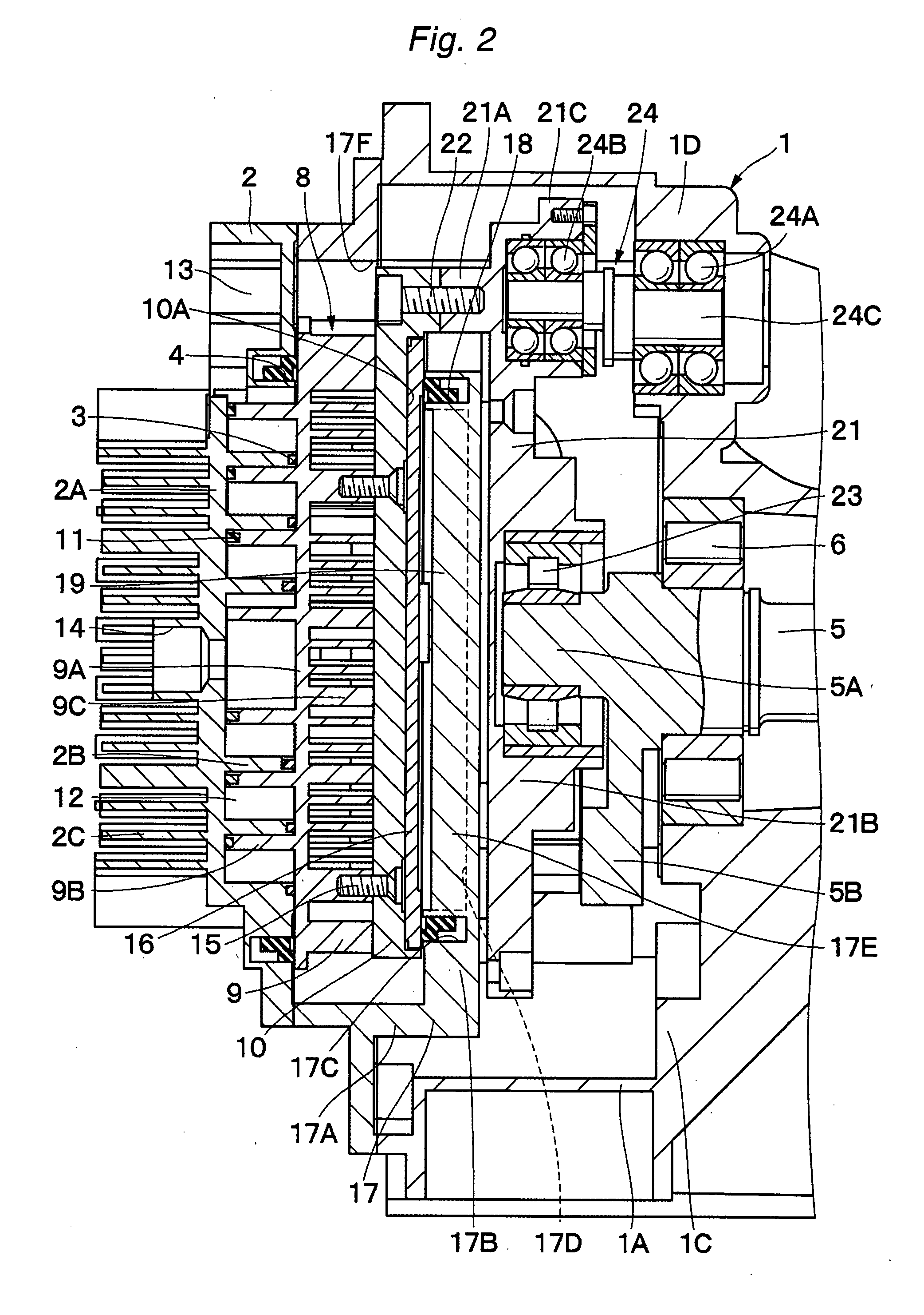
[0027]A scroll fluid machine according to an embodiment of the present invention will be described below in detail with regard to an air compressor, by way of example, with reference to the accompanying drawings.

[0028]In the figures, a tubular casing 1 forms an outer frame of a scroll fluid machine. The casing 1 has a large-diameter tube portion 1A and a bearing tube portion 1B having a smaller diameter than that of the large-diameter tube portion 1A and extending outward from one axial end of the large-diameter tube portion 1A. The casing 1 further has an annular portion 1C formed between the bearing tube portion 1B and the large-diameter tube portion 1A. The annular portion 1C is provided with three (for example) tubular bearing housing portions 1D that accommodate respective bearings 24A of auxiliary crank mechanisms 24 (described later). The bearing housing portions 1D are circumferentially equally spaced from each other.

[0029]A fixed scroll member 2 is attached to the casing 1 ...


PUM


Abstract

A scroll fluid machine is capable of readily providing a back-pressure chamber having an increased pressure-receiving area and yet capable of being reduced in size. A fixed scroll member is secured to a casing. An orbiting scroll member is provided at a position facing the fixed scroll member. A holder is provided at the back of the orbiting scroll member, and a coupling member is provided to face the orbiting scroll member across the holder. The coupling member couples together the orbiting scroll member and a driving shaft and performs an orbiting motion together with the orbiting scroll member. A back-pressure plate is provided at the back of the orbiting scroll member, and a back-pressure chamber is formed between the back-pressure plate and the holder.

Description

BACKGROUND OF THE INVENTION[0001]The present invention relates to a scroll fluid machine suitable for use as an air compressor, a vacuum pump, etc.[0002]In general, a scroll fluid machine includes a fixed scroll member and an orbiting scroll member that are disposed to face each other. The fixed and orbiting scroll members each have an end plate and a spiral wrap portion standing on the bottom surface of the end plate. The wrap portions of the two scroll members, which are disposed to face each other, overlap each other to define a plurality of compression chambers therebetween. In this state, the orbiting scroll member is driven to perform an orbiting motion with respect to the fixed scroll member, thereby successively contracting the compression chambers to compress a fluid, e.g. air.[0003]When compressed air is produced, the pressure of compressed air may apply an excessive thrust load to the orbiting scroll member in the direction of the rotating shaft. To minimize the thrust lo...

Claims


Application Information

Patent Timeline
Patent Type & Authority Applications(United States)
IPC IPC(8): F01C1/02
CPCF04C18/0215F04C27/005F04C18/0261
Inventor IWANO, KIMINORIKOMAI, YUJISUEFUJI, KAZUTAKAFUKUI, KOJISUZUKI, TOSHITSUGUNAGASAWA, JUNICHISAKAMOTO, SUSUMUHIDANO, KATSUSHIKOMATSU, KAZUNARI
Owner HITACHI LTD
Why Eureka
Try Eureka