Eureka AIR delivers breakthrough ideas for toughest innovation challenges, trusted by R&D personnel around the world.

Material neutral power generation

a technology of material neutrality and power generation, which is applied in the direction of electrochemical generators, bulk chemical production, greenhouse gas reduction, etc., can solve the problems of no competitiveness and/or pollution free energy transport, and the end user's "time of use" problem, etc., to achieve the effect of not disturbing or polluting the environmen

Inactive Publication Date: 2008-05-01
HYDROGEN ENGINE CENT
View PDF2 Cites 22 Cited by
  • Summary
  • Abstract
  • Description
  • Claims
  • Application Information

AI Technical Summary

Benefits of technology

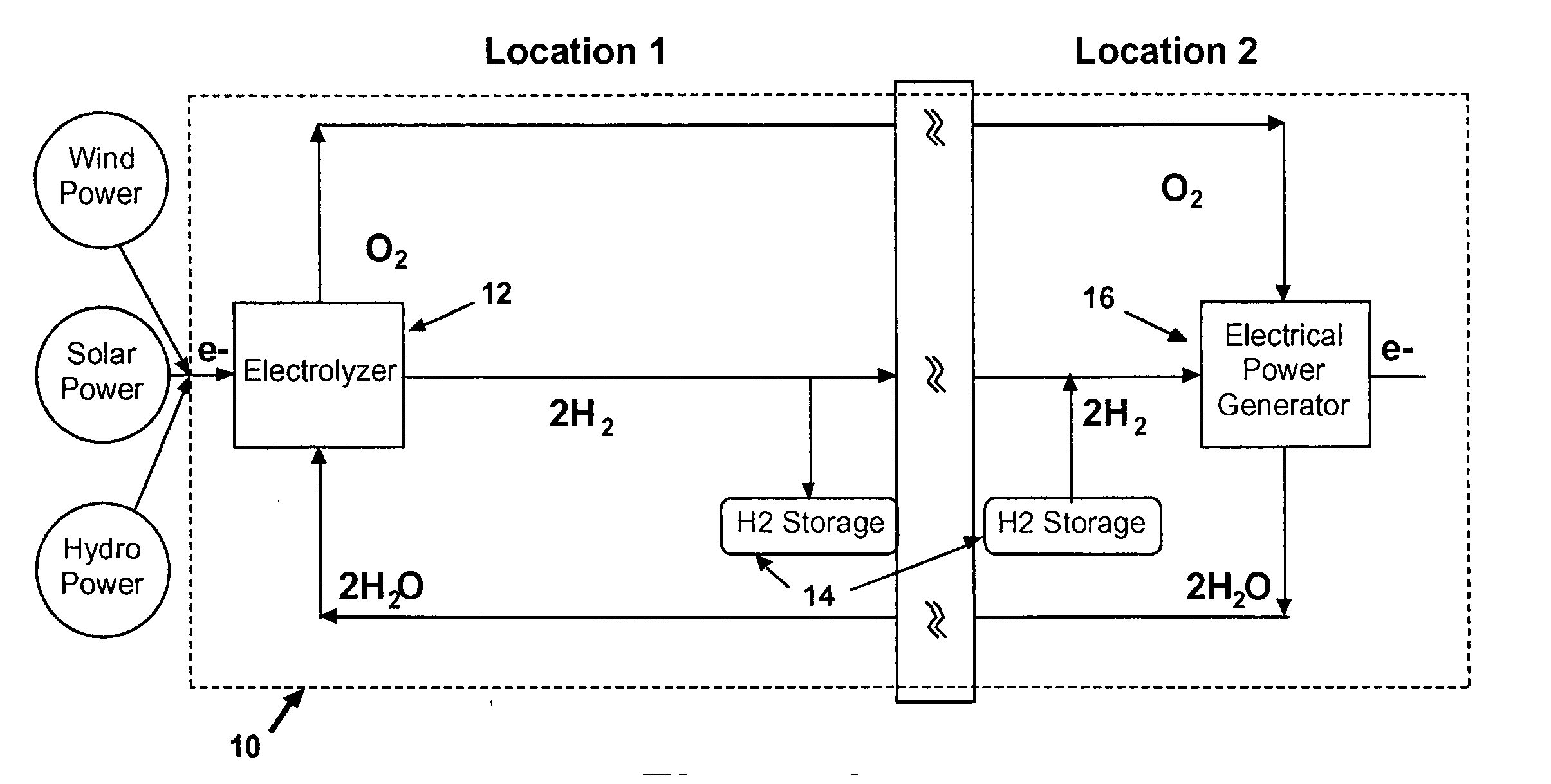
[0008] An object of the present invention is to provide a improved apparatus and method for converting and storing energy without disturbing or polluting the environment surrounding the apparatus.

Problems solved by technology

This lack of continuous power availability creates a “time of use” problem for the end user.
Various methods have been tried, including storage batteries, but none have proved to be competitive and / or pollution free.
Unfortunately, this is not near any of the world's population centers.
Transporting the energy then becomes a problem.
This problem is made worse if there are air quality concerns with the generation and / or the transportation of the energy.
In the case of wind, providing the grid with power late at night or very early in the morning is of little use since the grid can not really store energy, but can only route it to ready users of which there are few during these hours.
The use of diesel fuel to make electrical power is costly, both because of transportation and in terms of air pollution.

Method used


Image

  • Material neutral power generation
  • Material neutral power generation
  • Material neutral power generation

Examples


Embodiment Construction

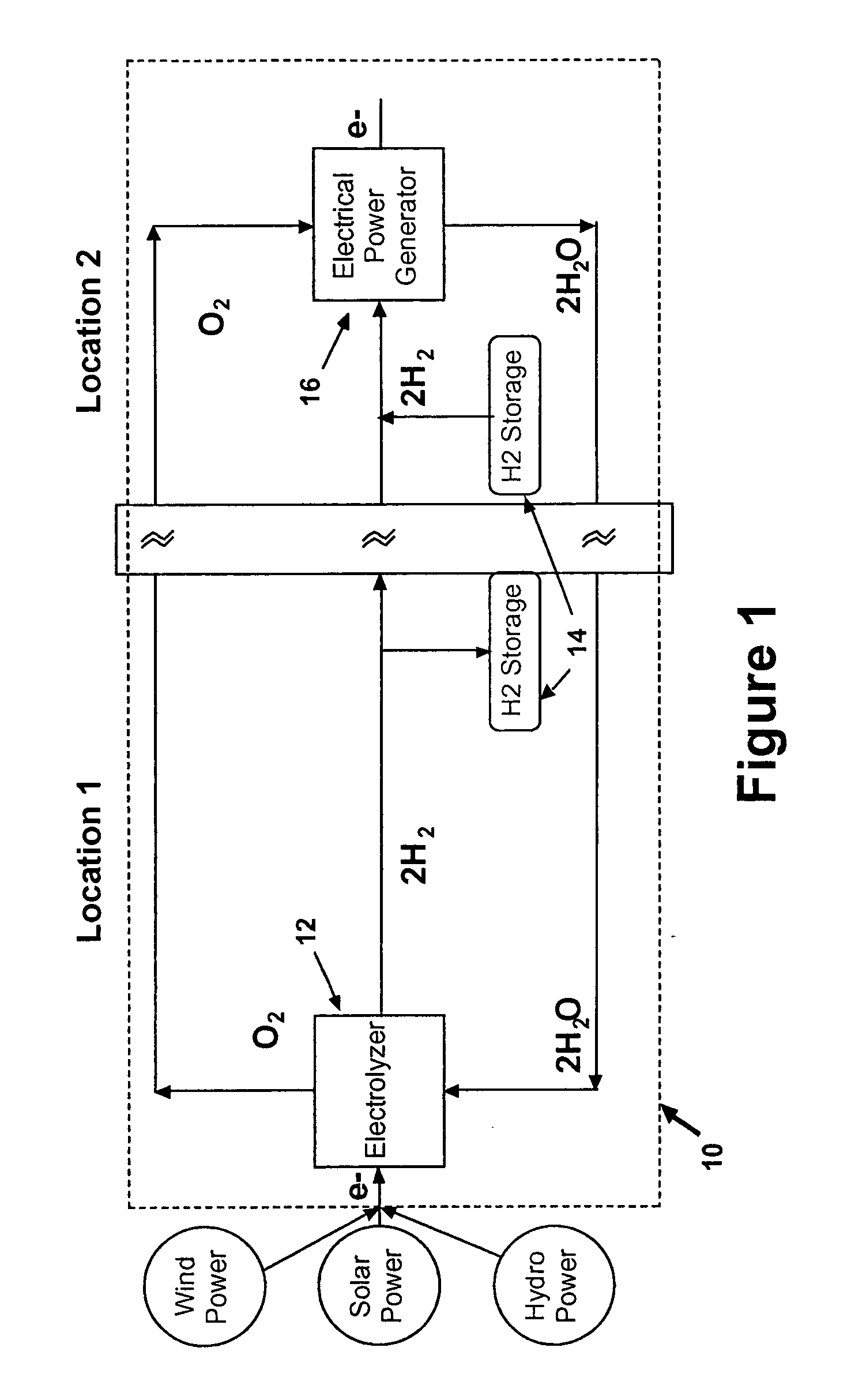
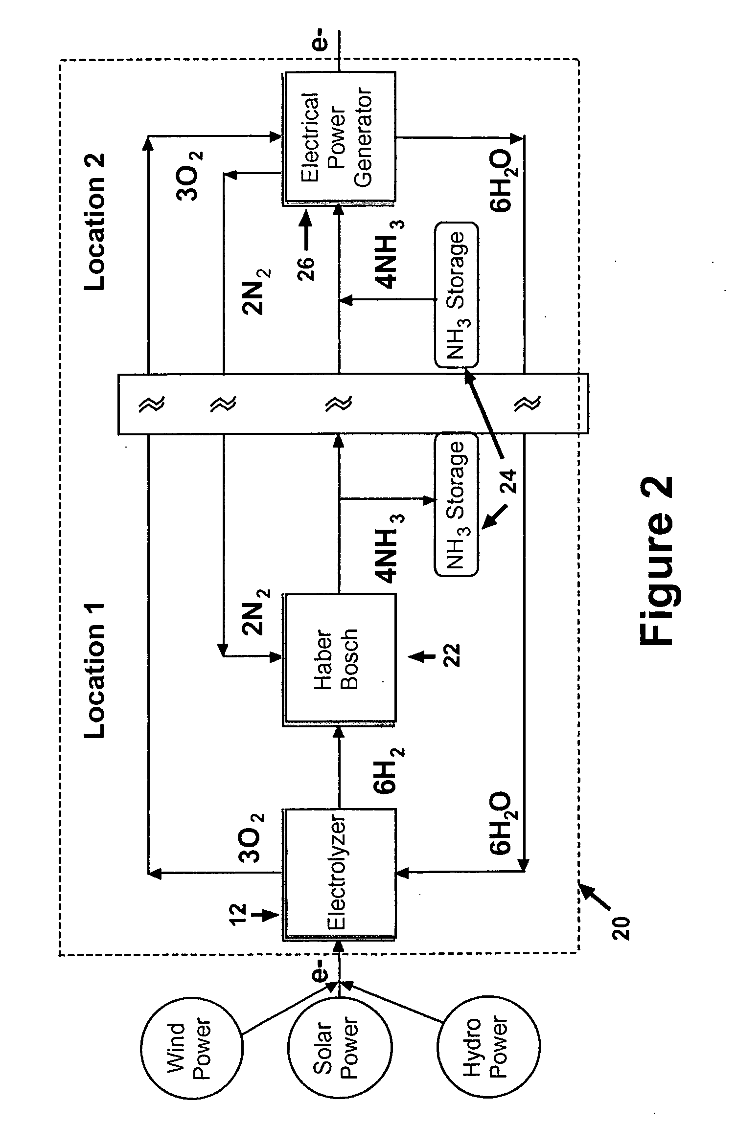
[0012]FIGS. 1 and 2 are schematic block diagrams of material neutral processes for generation of power. Each process begins with a renewable energy source such as wind, solar, geothermal or hydropower. This energy source is used to provide power to an electrolyzer for hydrogen separation. The electrolyzer separates hydrogen from oxygen by applying an electrical current to water. Thus, the inputs to the electrolyzer are electrical power and water. The outputs are hydrogen and oxygen.

[0013] In FIG. 2, the hydrogen from the electrolyzer is then combined with nitrogen to synthesize ammonia using conventional Haber-Bosch processing. The Haber-Bosch process reacts nitrogen and hydrogen to produce ammonia under very high pressure and moderately high temperatures. The process typically uses a catalyst made from iron in order to carryout the process at a lower temperature than is otherwise possible.

[0014] The resulting ammonia is then stored conventionally for delivery as fuel to a power s...


PUM

PropertyMeasurementUnit
energyaaaaaaaaaa
timeaaaaaaaaaa
renewable energyaaaaaaaaaa

Abstract

A renewable electrical power generation system is provided having energy storage and a power generation system to convert the stored energy to electrical power to ensure the end user with a continuous source of electrical power. The system comprises a renewable energy to electrical power unit plus a system to convert electricity to fuel (hydrogen and / or ammonia) with the required associated fuel storage and a fuel to electricity unit (engine and generator and / or fuel cell). This system has a monitor and control system that ensures proper operation such that the end user receives electrical power in the most efficient way.

Description

BACKGROUND OF THE INVENTION [0001] The present invention relates to the generation of power from a renewable source, particularly an intermittent source such as wind or solar, in a manner that has energy storage that allows the user an unlimited time of use. More specifically, the invention comprises a renewable electrical power source, an electrolyzer to convert the electricity to hydrogen, a storage unit to hold the hydrogen, an electric power generation unit that converts the hydrogen to electricity, such as an internal combustion engine and associated generator or a fuel cell and associated electronics, and a control system to monitor and control the process. [0002] Renewable power generation systems are generally intermittent power sources because the energy source, such as wind or solar, are not continuous. This lack of continuous power availability creates a “time of use” problem for the end user. The solution to this problem is to store the renewable energy for use at any de...

Claims


Application Information

Patent Timeline
Patent Type & Authority Applications(United States)
IPC IPC(8): H01M8/04
CPCH01M16/003C25B1/04F02M25/12F02B2043/106C01C1/0488Y02T10/32Y02E70/10Y02E70/20Y02E60/366Y02T10/121F02M21/0206Y02E60/36Y02E60/50Y02T10/12Y02T10/30Y02P20/133Y02P20/52
Inventor HOLLINGER, TED
Owner HYDROGEN ENGINE CENT
Why Eureka
Eureka Blog
Learn More