Accelerometer derived gyro vibration rectification error compensation

Inactive Publication Date: 2008-05-08
HONEYWELL INT INC
View PDF5 Cites 31 Cited by
  • Summary
  • Abstract
  • Description
  • Claims
  • Application Information

AI Technical Summary

Benefits of technology

[0009]In one non-limiting embodiment, each of three MEMS gyroscopes are mounted on a base and situated to measure rotation about each of a first set of three mutually orthogonal axes. Similarly, three accelerometers are mounted on the base to measure vibration along each of a second set of three mutually orthogonal axes. The first and second set of three mutually orthogonal axes need not coincide, as translation of measured vibration along each of the second set of three mutually orthogonal axes into components along the first set of three mutually orthogonal axes is readily accomplished.
[0010]From vibration along each of the second three mutually orthogonal axes, an acceleration vector normal to the gyro sensor is determined and used as input to a computer model for real-time compensation. In calibration, a coefficient of a polynominal are determined that indicates the gyro's tendency to VRE. The coefficients are maintained in the IMU through the manufacture process in a processor-readable coefficient file, and constitutes a portion of the software d

Problems solved by technology

VRE severely degrades the output of the MEMS gyroscope.
Vibration in the axis normal to the plane describing MEMS proof mass vibration can cause excess deflect

Method used


Image

  • Accelerometer derived gyro vibration rectification error compensation
  • Accelerometer derived gyro vibration rectification error compensation
  • Accelerometer derived gyro vibration rectification error compensation

Examples


Embodiment Construction

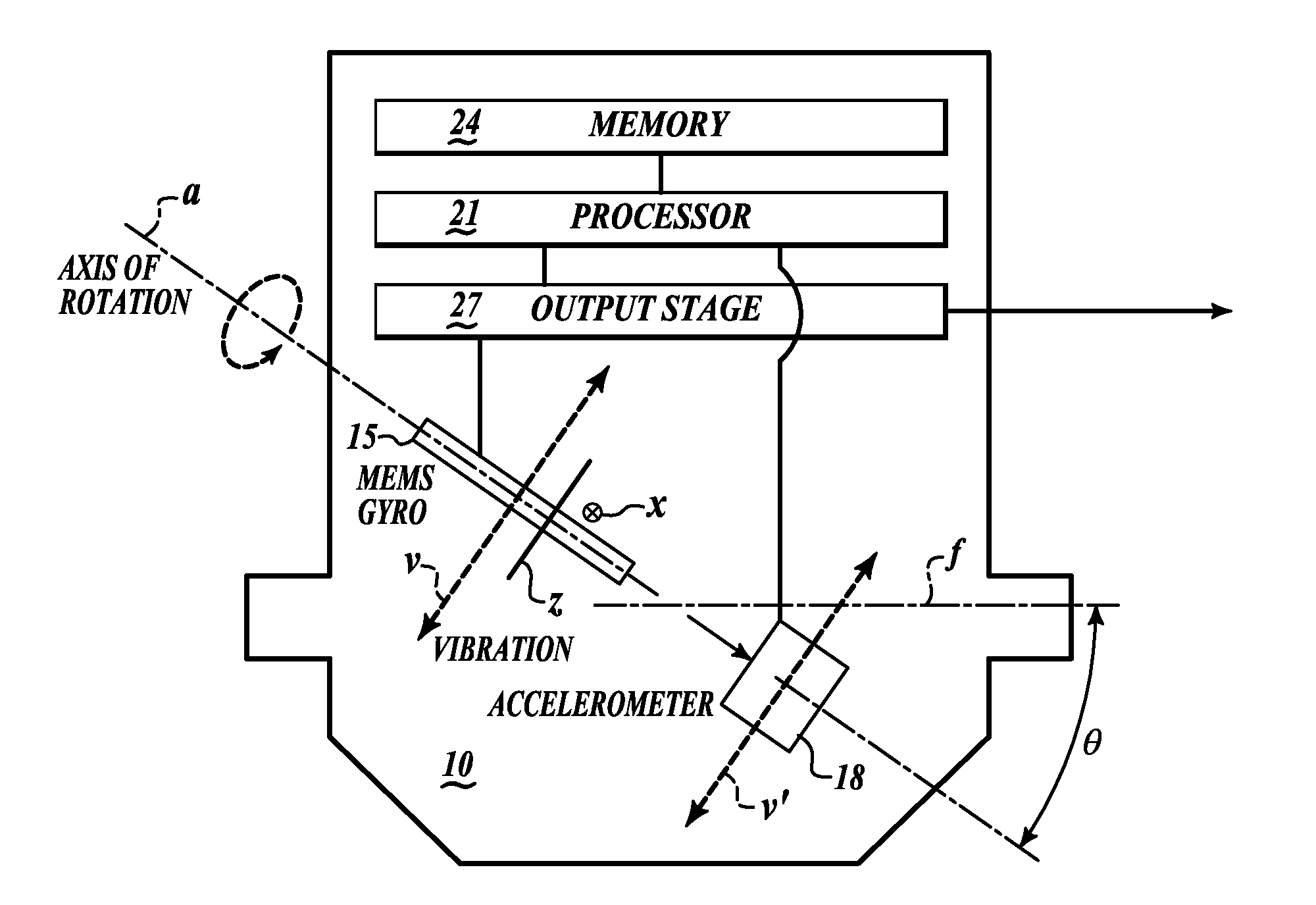
[0015]An apparatus compensates for vibration rectification error present in a MEMS gyroscope output signal. The MEMS gyroscope has an axis of rotation normal to an operative plane. The apparatus includes at least one accelerometer situated to generate an acceleration signal indicating acceleration along the axis of rotation. A processor generates a compensation signal based upon the acceleration signal. An output stage amplifies the gyroscope output signal according to the compensation signal. The processor retrieves compensation data from a processor-readable memory according to the acceleration signal. The compensation signal is further based upon the compensation data.

[0016]Referring to FIG. 1, the MEMS gyroscope 15 is seen in side view mounted on the mount 10 at a sense angle θ to a flange plane f. The MEMS gyroscope 15 operates to sense rotational acceleration about an axis of rotation a. The MEMS gyroscope 15 characteristically have an axis of rotation a, defining the Coriolis...


PUM


Abstract

An apparatus compensates for vibration rectification error present in a MEMS gyroscope output signal. The MEMS gyroscope has an axis of rotation normal to an operative plane. The apparatus includes at least one accelerometer situated to generate an acceleration signal indicating acceleration along the axis of rotation. A processor generates a compensation signal based upon the acceleration signal. An output stage amplifies the gyroscope output signal according to the compensation signal. The processor retrieves compensation data from a processor-readable memory according to the acceleration signal. The compensation signal is further based upon the compensation data.

Description

PRIORITY CLAIMBackground of the Invention[0001]A Microelectromechanical Systems (MEMS) is vibrating proof mass structure gyroscope configured on a scale of from a micrometer (a millionth of a meter) to a millimeter (thousandth of a meter) in overall length. Generally MEMS gyroscopes are fabricated using modified silicon fabrication technology (used to make electronics), molding and plating, wet etching (KOH, TMAH) and dry etching (RIE and DRIE), electro discharge machining (EDM), and other technologies. MEMS fabrication is readily accomplished in conjunction with fabrication of attendant driver circuitry supporting the MEMS gyroscope in Inertial Measurement Units (IMUs) which are, in turn, used in navigation.[0002]In the MEMS gyroscope, movement of a vibrating proof mass is used to measure acceleration. A vibrating object tends to keep vibrating in the same plane even as its support is rotated. Measuring the deflection of the vibrating object relative to the support yields a measure...

Claims


Application Information

Patent Timeline
IPC IPC(8): G01P15/00
CPCG01C19/5719
Inventor KRAETZ, WILLIAM F.
Owner HONEYWELL INT INC
Why Eureka
Try Eureka