Stereoscopic image capturing method, system and camera

a stereoscopic image and camera technology, applied in the field of system a camera for recording image data, can solve the problems of ultra precise alignment requirements between the two cameras, affecting the quality of video images, so as to avoid any problems with lens alignment

Inactive Publication Date: 2015-09-08
KONINKLIJKE PHILIPS ELECTRONICS NV
View PDF14 Cites 1 Cited by
  • Summary
  • Abstract
  • Description
  • Claims
  • Application Information

AI Technical Summary

Benefits of technology

[0012]The inventors have realized that by using an optical device which creates a compound image, i.e. an image comprising a left and right (or from more directions taken) image taken simultaneously it is possible to determine the distance of a recorded object to the lens, and thereby create a depth map for the recorded image. There is no need for two cameras and thus the need for accurate alignment of the cameras does not occur. The images are taken simultaneously and thus problems with shift of moving objects due to motion of the objects between the times the left and right images are taken are eliminated. Analysis of the compound image allows, e.g. by deconvolution of the compound image, to extract the two or more, simultaneously taken, constituting images of the compound image. This allows determining the distance in pixels or in cm between corresponding objects in the recorded compound image. The distance in the compound image can then be easily translated in distance to the lens, since it is only determined by this distance.
[0014]a grating. Gratings create, by diffraction, next to the main image side images of objects in a recording plane. The distance between an object in the main image and in the side images is directly dependent on the distance to the lens. Apart from this dependence the said distance is also dependent on the wavelength of the light. This embodiment is very useful where use is made of light of known wavelength, or of nearly monochromatic light, since this simplifies the calculations.
[0022]The latter type has the advantage, in comparison to the first type, that it is possible to see to some extent behind a foreground object, since two images of slightly different viewing point are used.
[0033]If a single image, i.e. non-compound, image is known, the information obtained on the simple image allows a relatively easier extracting of the constituting images from the compound image and / or a relatively reliable check on results and / or a relatively easy reconstruction of one of the constituting images. Essential to the invention is, however, that compound images are taken wherein
[0036]The first feature, i.e. the simultaneous recording of the constituting images, eliminates any problem of shift in position of objects due to motion of an object between the times the constituting images are taken.
[0037]The second feature eliminates any problem due to uncertainty in alignment of sensor or differences between sensors. Preferably the constituting images are also taken through the same lens to avoid any problems with alignment of lenses.

Problems solved by technology

Although much progress has been made in stereovision, the fundamental correspondences problem remains difficult in real-world applications.
In particular, the ultra precise alignment requirements between the two cameras hamper cheap consumer applications.
However, although this may work well for a single image, for video images wherein objects are moving around this becomes very difficult.
Using a variable lens while at the same time recording video images with changing content constitutes a daunting task, requiring very fast variable lenses and massive computing power.
Also, it cannot be used in a known camera, if it does not have a variable lens with the required speed and scope of focus variation.
However they are generally expensive and have limited spatial resolutions (e.g., 64×64 for a Canesta sensor).
At short distances it becomes, due to the short time of flight, difficult to measure anything at all.
Recording alternatively left and right images works fine for static objects, but has the disadvantage that for moving objects left and right images are not the same since objects have moved between taking the images.
In circumstances, such as moving repetitive patterns or objects moving at great speed or having an erratic motion, accurate motion estimation is hardly or at all possible.

Method used


Image

  • Stereoscopic image capturing method, system and camera
  • Stereoscopic image capturing method, system and camera
  • Stereoscopic image capturing method, system and camera

Examples


Embodiment Construction

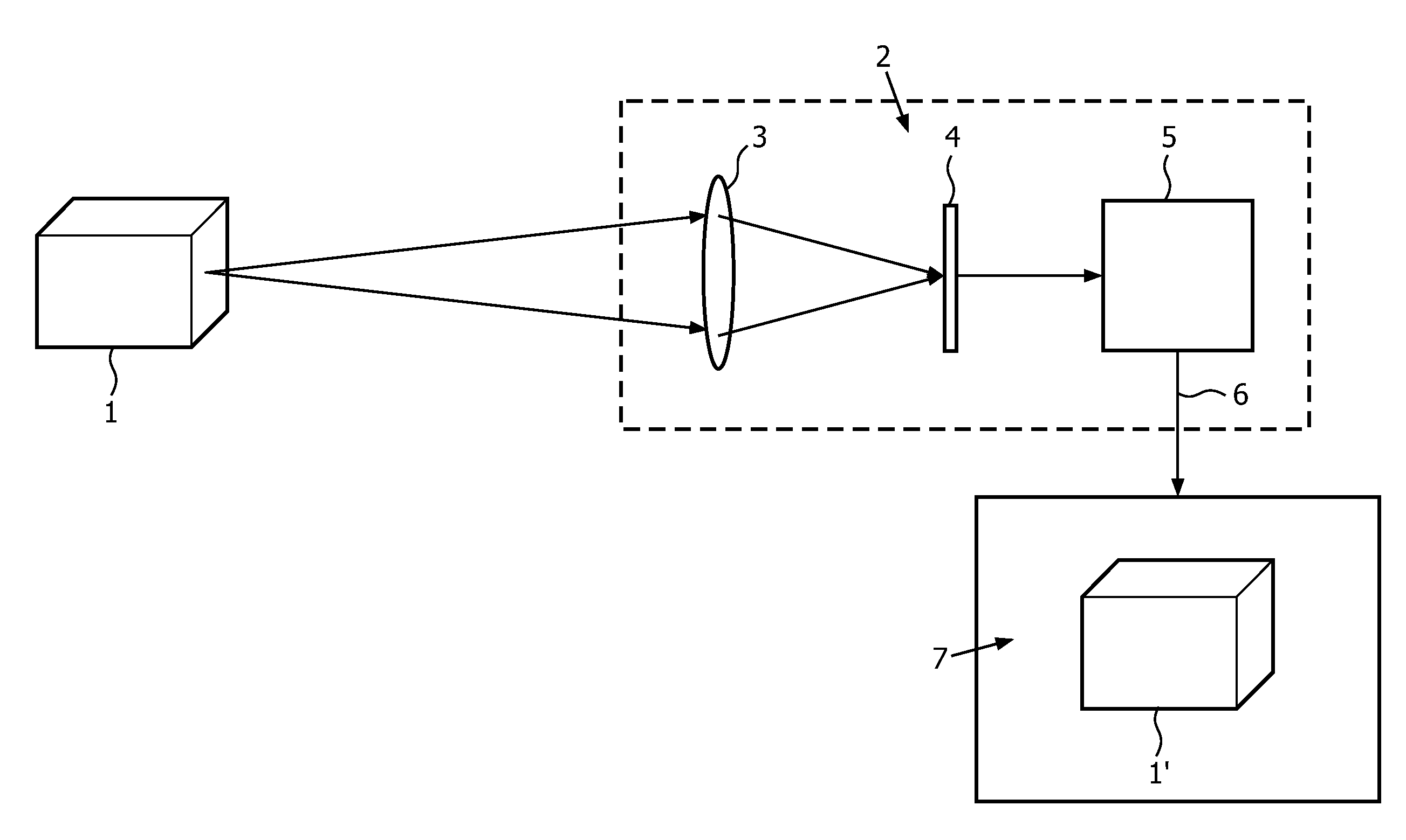
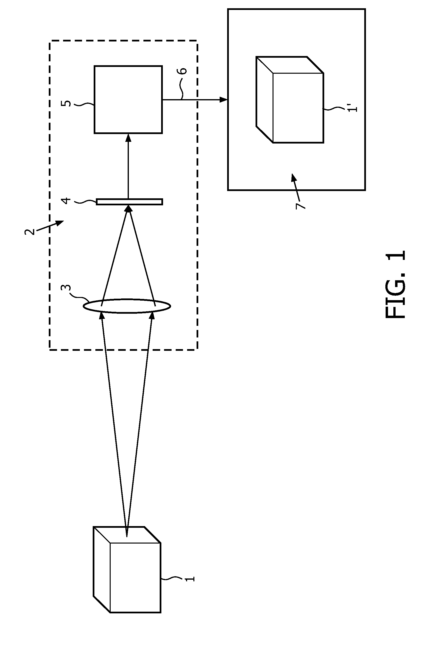
[0051]FIG. 1 schematically illustrates a system, method and camera to record images.

[0052]The object 1 is captured by lens 3 of camera 2. The image is focused on sensor 4, for instance a CCD. This device produces a signal which is converted into signal 6 by for instances an encoder 5. The encoder 5 could do some image enhancement or otherwise improve the image signal.

[0053]The signal can be sent, either in encoded form or directly to a display device having a display 7 on which an image 1′ is visible. The signal 6 can also be stored on some type of storage medium.

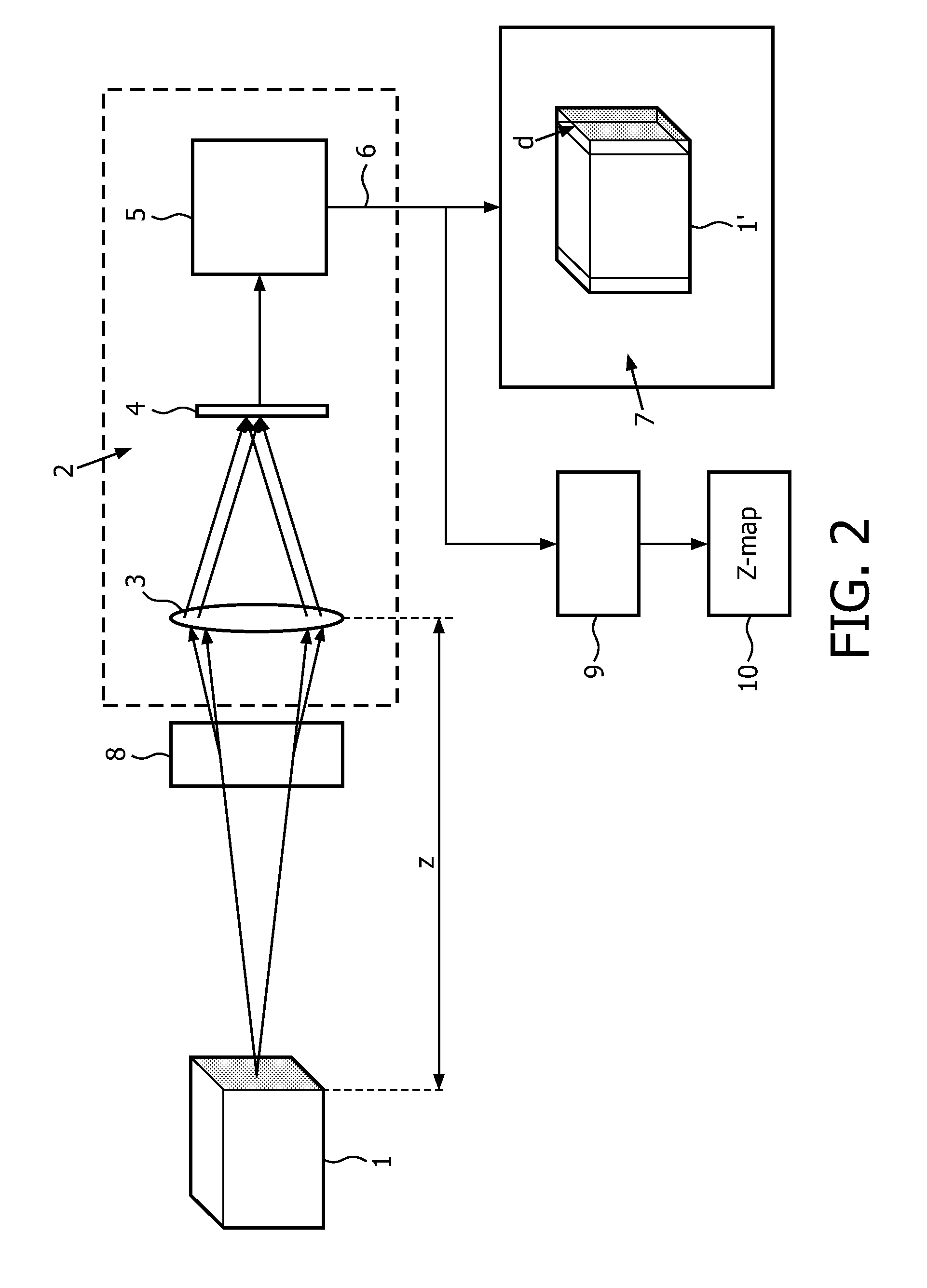
[0054]FIG. 2 schematically illustrates a system, method and camera to record image data in accordance with the invention.

[0055]In front of the lens, an optical device 8 is positioned. The optical device can be positioned at some distance from the camera or attached to the camera. The optical device creates two or more superimposed images on the sensor. On the display 7, one would see two or more constituting images, slightl...


PUM


Abstract

A camera and camera system is provided with an optical device (8). The optical device creates simultaneously two or more images of object on a sensor (4) forming a compound image. The distance d between the constituting images of objects in the compound image is dependent on the distance Z to the camera. The compound image is analyzed (9), e.g. deconvolved to determine the distances d between the double images. These distances are then converted into a depth map (10).

Description

FIELD OF THE INVENTION[0001]The invention relates to a system for recording image data, a method for recording image data and a camera for recording image data.BACKGROUND OF THE INVENTION[0002]Recently there has been much interest in providing 3-D images on 3-D image displays. It is believed that 3-D imaging will be, after color imaging, the next great innovation in imaging. We are now at the advent of introduction of 3D displays for the consumer market.[0003]A 3-D display device usually has a display screen on which the images are displayed. Basically, a three-dimensional impression can be created by using stereo images, i.e. two slightly different images directed at the two eyes of the viewer. An example of such a device is an autostereoscopic display. In other devices images are sent in all directions and glasses are used to block certain images to give a 3D perception.[0004]Whatever type of 3-D display is used, the 3-D image information has to be provided to the display device. ...

Claims


Application Information

Patent Timeline
Patent Type & Authority Patents(United States)
IPC IPC(8): H04N13/00H04N13/02
CPCH04N13/0217H04N13/0003H04N13/0207H04N13/0289H04N13/218H04N13/10H04N13/207H04N13/289
Inventor VLUTTERS, RUUDDE BRUIJN, FREDERIK JANZNAMENSKIY, DMITRY NIKOLAEVICH
Owner KONINKLIJKE PHILIPS ELECTRONICS NV
Why Eureka
Try Eureka