Implantable Devices Based on Magnetoelectric Antenna, Energy Harvesting and Communication

a technology of magnetoelectric antenna and implantable device, applied in the field of human brain research, to achieve the effect of improving signal-to-noise ratio, reducing tissue conductivity, and improving spatial specificity for signal propagation

Pending Publication Date: 2020-05-07
NORTHEASTERN UNIV
View PDF25 Cites 3 Cited by
  • Summary
  • Abstract
  • Description
  • Claims
  • Application Information

AI Technical Summary

Benefits of technology

[0011]Neural stimulation using magnetic fields has substantial advantages over stimulation using electric fields. Electric field stimulation is a consequence of the local gradient of the electric potential, which is complicated by tissue conductivity. Magnetic activation, on the other hand, is sensitive to non-local field sources, but the drop in magnetic field strength occurs as the cube of the distance. This provides better spatial specificity for signal propagation, producing an effective increase in signal-to-noise ratio (SNR) at the stimulation site. Perhaps more importantly, the magnetic field is not impacted by changes in tissue composition. This makes stimulating with magnetic fields much simpler and more straightforward, and facilitates full hermetic encapsulation of the device.
[0012]Further, neural magnetic sensing is not referential, which enables significantly more compact implantable devices. Neural magnetic sensing facilitates sensing individual neuronal activity, which allows for better separation of individu

Problems solved by technology

Electric field stimulation is a consequence of the local gradient of

Method used


Image

  • Implantable Devices Based on Magnetoelectric Antenna, Energy Harvesting and Communication
  • Implantable Devices Based on Magnetoelectric Antenna, Energy Harvesting and Communication
  • Implantable Devices Based on Magnetoelectric Antenna, Energy Harvesting and Communication

Examples


Embodiment Construction

[0047]A description of example embodiments follows.

[0048]The teachings of all patents, published applications and references cited herein are incorporated by reference in their entirety.

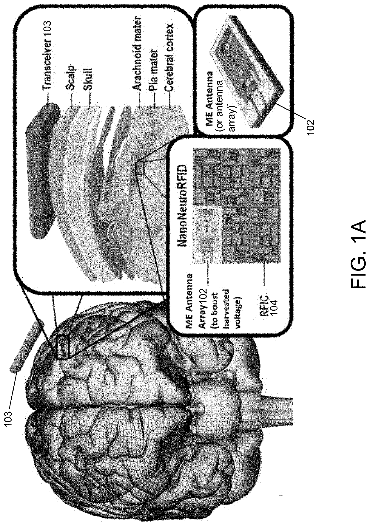
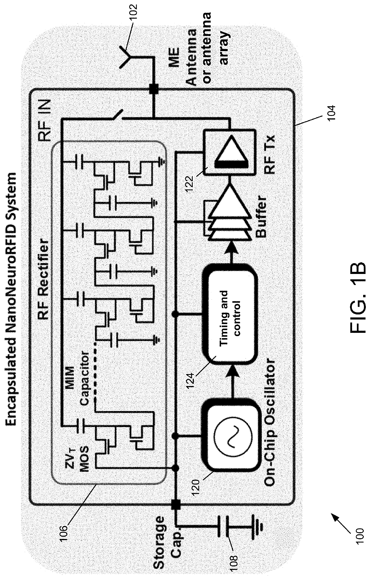
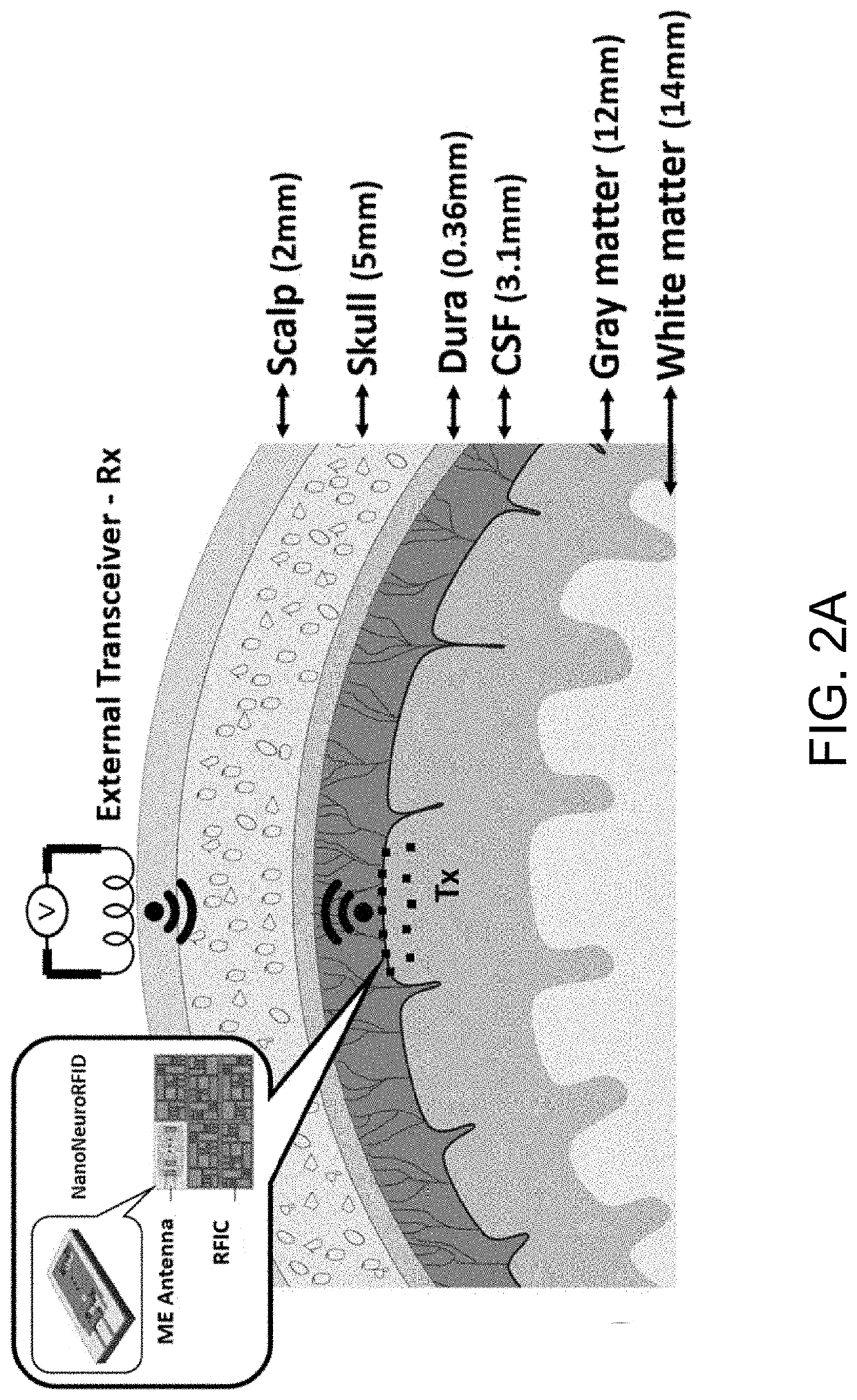
[0049]Embodiments of the implantable system described herein are directed to a wireless, sub-millimeter (mm) sized, and self-powered implantable device, which may be suitable for large-scale in-vivo neural magnetic field recording. FIGS. 1A and 1B illustrate conceptual block diagram and architecture of an example embodiment of the implantable system 100.

[0050]At the core of described implantable system 100 is an ultra-compact, acoustically actuated magnetoelectric (ME) antenna 102. The ME antenna 102, which is a nanoplate resonator (NPR), is one to two orders of magnitude smaller than comparable loop antennas, and have at least a 50 dB higher antenna gain. The ME antenna 102 is sensitive to a neural magnetic signal, in that the resonance frequency of ME antenna shifts when it is in presence of a DC o...


PUM


Abstract

Disclosed is an implantable system that comprises a magnetoelectric (ME) antenna, a radio frequency rectifier, and a transmitter. The ME antenna may be characterized by a resonance frequency that changes according to an ambient magnetic field strength. The radio frequency rectifier may be configured to convert radio frequency energy, received by the ME antenna, into a direct current voltage, and to direct the direct current voltage to a storage capacitor. The transmitter may be configured to apply a transmission signal to the ME antenna. A transceiver may communicate with one or more of the implantable systems, to provide radio frequency energy to the implantable devices for energy harvesting, and to receive transmitted information from the implantable systems. The implantable system may be disposed within a brain to detect neuronal activity, by detecting small magnetic fields generated by such neuronal activity.

Description

RELATED APPLICATION(S)[0001]This application claims the benefit of U.S. Provisional Application No. 62 / 754,145, filed on Nov. 1, 2018. The entire teachings of the above application are incorporated herein by reference.GOVERNMENT SUPPORT[0002]This invention was made with government support under Grant No. 1160504 from the National Science Foundation and Grant No. D15PC00009 from DARPA. The government has certain rights in the invention.BACKGROUND[0003]Important aspects of human brain research are the ability to record brain signals, and to stimulate neurons, with a very high spatial and temporal resolution. To date, many tethered and tether-less devices have been developed for neural modulation purposes. It can be a great challenge to obtain a high density distributed network of tethered (optical or electrical) devices due to wiring and interconnection constraints related to such devices. Tethered devices may also suffer from safety problems related to bio-compatibility and insulatio...

Claims


Application Information

Patent Timeline
IPC IPC(8): H01L41/12H01Q1/22A61N1/378H01Q1/24A61N1/372
CPCH01L41/12A61N1/37229H01Q1/248H01Q1/2283A61N1/3787A61N2/006A61N2/02A61B5/0031A61B5/686A61B5/6861A61B5/6868A61B5/7225A61B2560/0219A61B2562/0223A61B2562/043A61B2562/162A61B5/245H10N30/00H10N35/00
Inventor SUN, NIAN XIANGZAEIMBASHI, MOHSENLIN, HWAIDER
Owner NORTHEASTERN UNIV
Why Eureka
Try Eureka