Manufacturing Method of Water Block

Inactive Publication Date: 2008-05-08
COOLER MASTER CO LTD
View PDF5 Cites 34 Cited by
  • Summary
  • Abstract
  • Description
  • Claims
  • Application Information

AI Technical Summary

Benefits of technology

[0011] Therefore, the present invention is to provide a water block having porous microchannels and its manufacturing method, and a thermal conducting powder is sintered to form a porous microchannel structure that can produce a turbulent flow effect on a coolant and greatly improve the staying time of co

Problems solved by technology

The operation of any electric appliance may cause overheats inevitably due to the issue of efficiency or friction.
A fan is a simple, easy and popular heat dissipating device which can produce a fast flow of air around a heat generating component by vanes, and quickly carry away the heat produced by heat generating components to achieve the heat dissipation effect, but the heat dissipating effect may not be able to satisfy the efficiency required for the heat conduction due to an insufficient heat dissipating area, and thus the actual heat dissipating efficiency is below the expected efficiency.
Further, a fan can be used for blowing and carrying away the heat source compulsorily, but the airflow volume of the fan is very limited, and the heat dissipating effect still cannot be improved effectively.
Thus, prior arts try to improve the airflow volume by connecting a plurality of fans in series, but such arrangement is limited by the available space and it is very difficult to implement.
Furthermore, an increase of the rotary speed of a motor for improving the airflow volume gives rise to a higher level of difficulty for manufacturing the motor, and the increase of the rotary speed of a motor h

Method used


Image

  • Manufacturing Method of Water Block
  • Manufacturing Method of Water Block
  • Manufacturing Method of Water Block

Examples


Embodiment Construction

[0029] The technical characteristics, features and advantages of the present invention will become apparent in the following detailed description of the preferred embodiments with reference to the accompanying drawings. However, the drawings are provided for reference and illustration only and are not intended for limiting the scope of the invention.

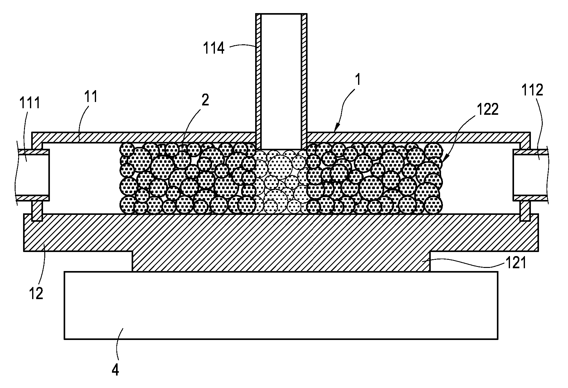
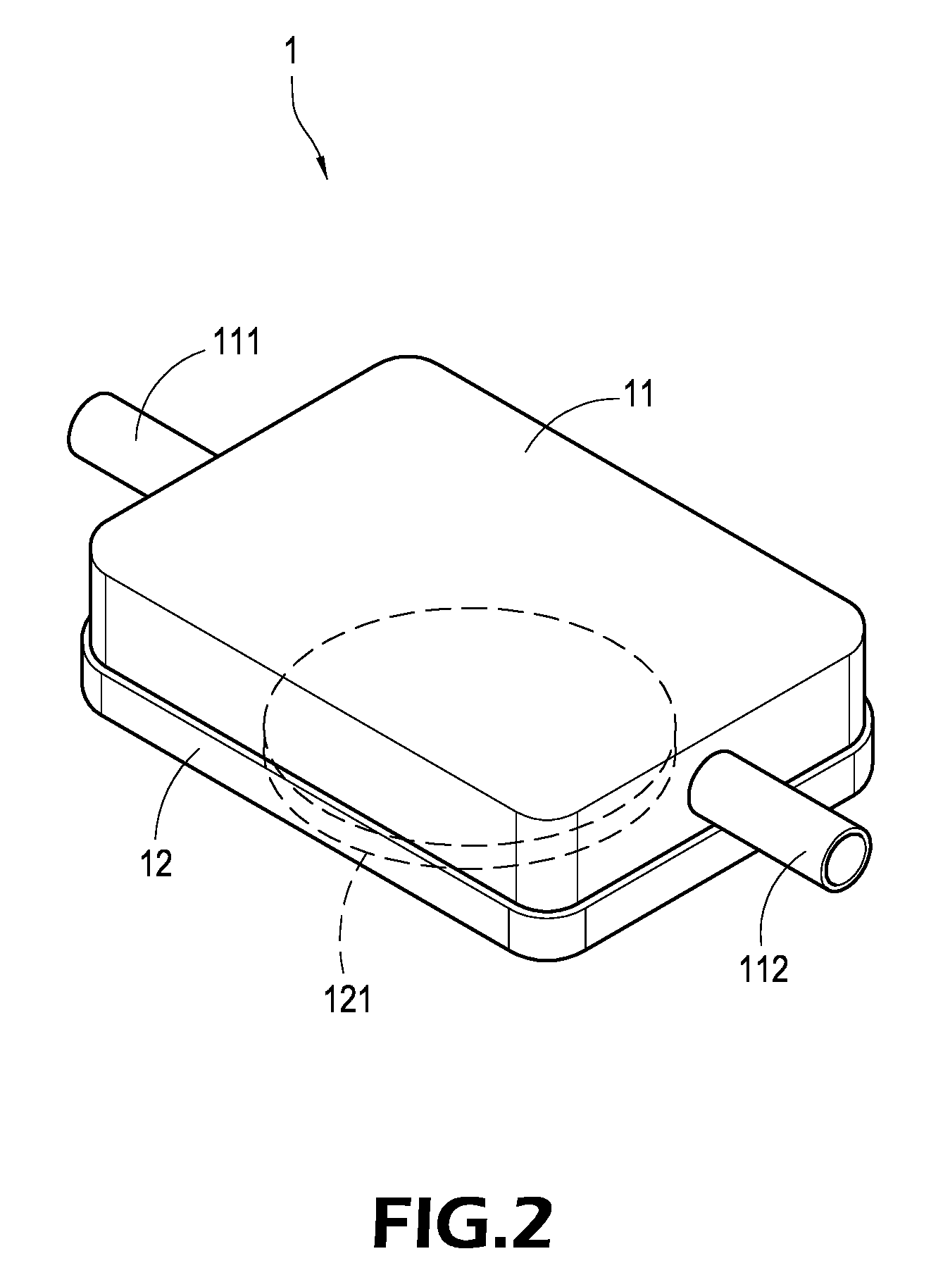
[0030] Referring to FIG. 2, a water block body 1 of the invention comprises a first casing 11 and a second casing 12 engaged with each other to form a hollow sealed box body, and the shape of the water block body 1 can be varied appropriately according to different requirements. The first casing 11 and the second casing 12 of this embodiment are cuboids (but not limited to such arrangement) made of a metal material or a ceramic material. The first casing 11 and the second casing 12 are coupled by soldering, riveting or binding. In addition, the first casing 11 has a water inlet pipe 111 and a water outlet pipe 112 extended outward (or u...


PUM


Abstract

A porous microchannel structure adopts a first casing and a second casing to form a water block. Water inlet and outlet pipes are extended from both ends of the first casing respectively. The second casing has a porous microchannel structure made by sintering a heat conducting powder and formed on an internal side of the second casing. The second casing has a contact surface on its external side for absorbing and conducting a heat source to the porous microchannel structure, such that a coolant can flow from the water inlet pipe into the water block. The porous microchannel structure produces turbulent flows to the coolant, so as to extend the staying time of the coolant in the water block, and allow the coolant to fully exchange heat with the porous microchannel structure and flow out from the water outlet pipe.

Description

[0001] This application is a divisional application of U.S. patent application Ser. No. 11 / 549,673, filed on Oct. 16, 2006.BACKGROUND OF THE INVENTION [0002] 1. Field of the Invention [0003] The present invention relates to a water-cooling heat dissipating structure and its manufacturing method, and more particularly to a water block applicable for electronic components and its manufacturing method. [0004] 2. Description of Prior Art [0005] The operation of any electric appliance may cause overheats inevitably due to the issue of efficiency or friction. Particularly, products produced by manufacturers of the present technological industry such as integrated circuits and personal electronic products tend to be developed with a high precision. Besides the minimization of volume, these products (particularly computers) also produce increasingly more heat. Since the operation performance of these products is enhanced continuously, the overall heat quantity produced by computes is also i...

Claims


Application Information

Patent Timeline
IPC IPC(8): F28D13/00
CPCF28D2021/0029F28F3/048F28F2255/18F28F13/185F28F3/12
Inventor PENG, YU-HUANG
Owner COOLER MASTER CO LTD
Why Eureka
Try Eureka